05-12-2012, 06:02 PM
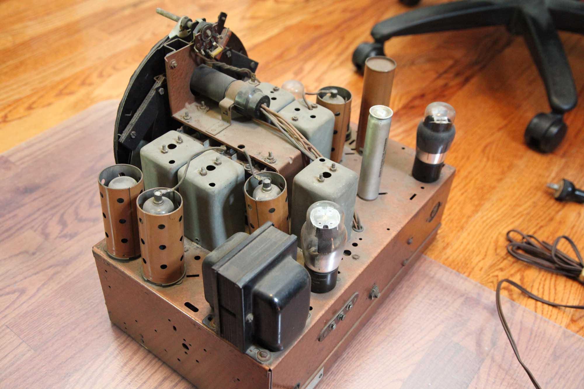
Well, here's my 9S262.
Took it apart.
Here it is.
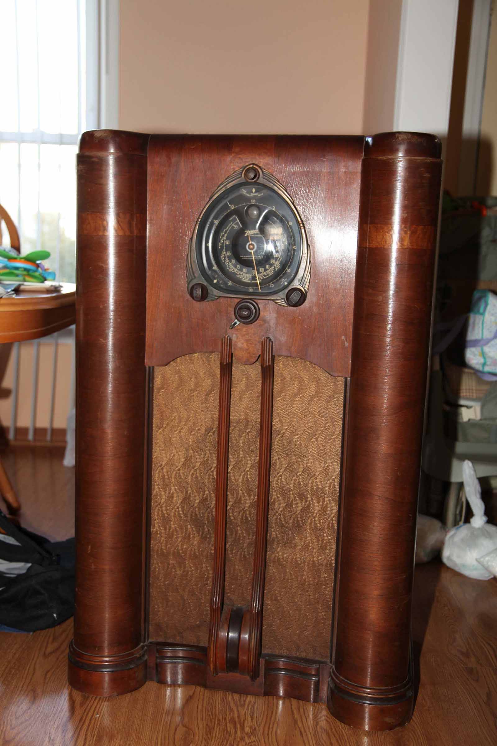
Back view.
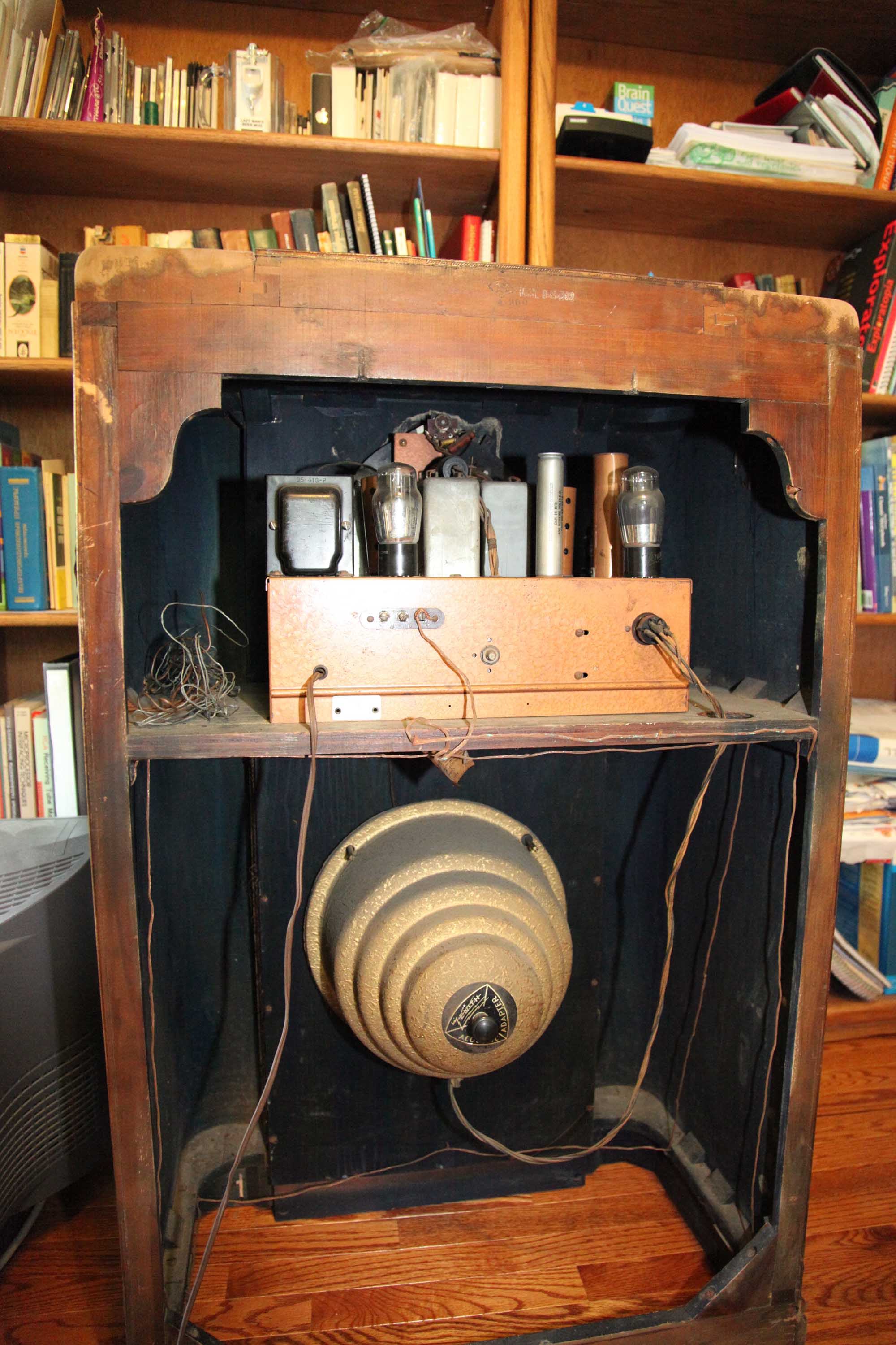
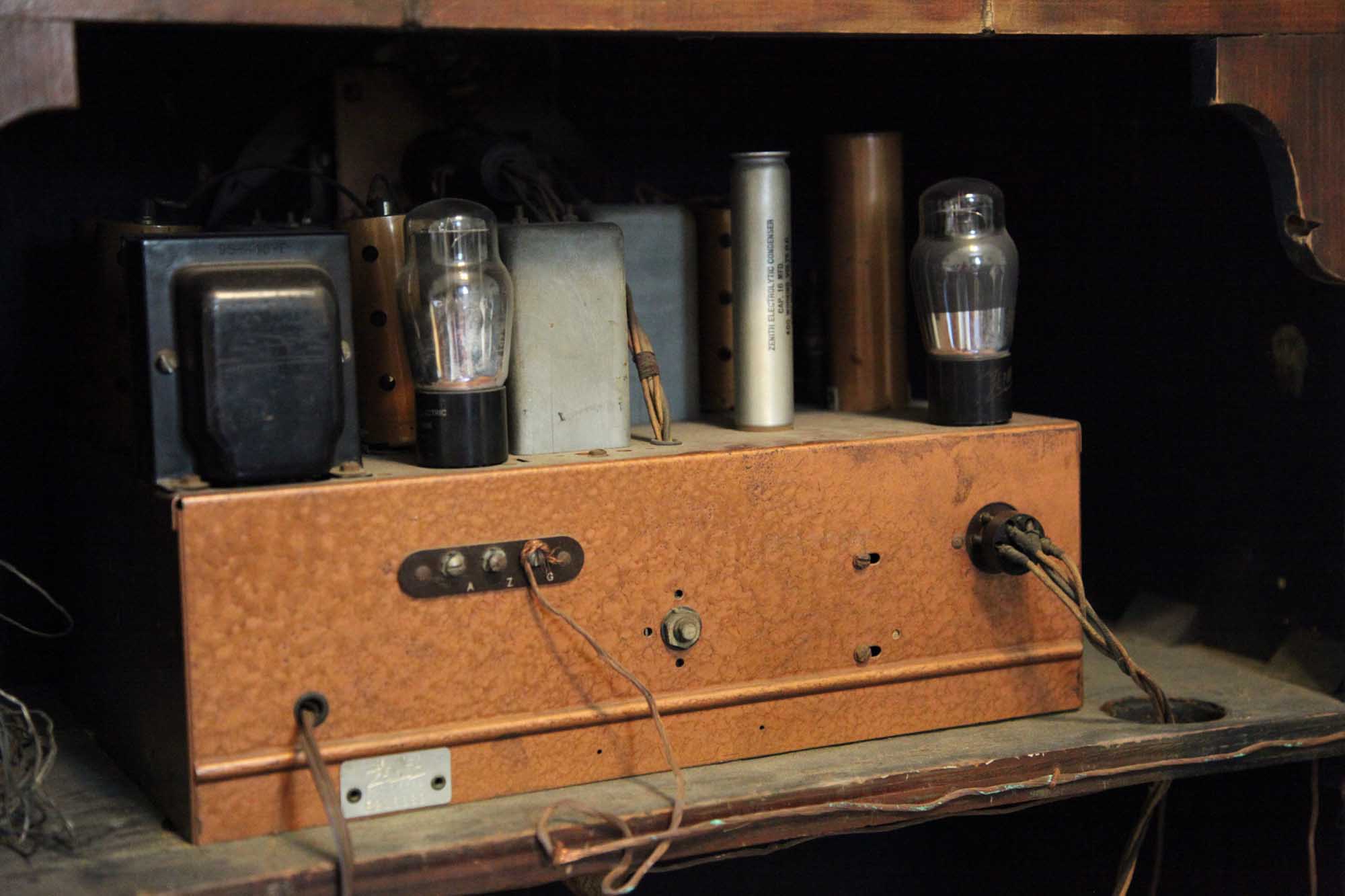
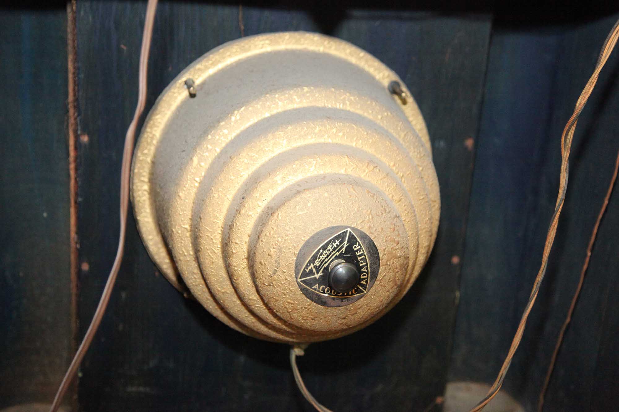
Top view
Took it apart.
Here it is.
Back view.
Top view
|
9S262 - getting started
05-12-2012, 06:02 PM
Well, here's my 9S262.
Took it apart. Here it is. Back view. Top view
05-12-2012, 06:04 PM
Bottom view.
The seller told me he heard the motor run but the tuning did not work. This is, I think, the reason.
05-12-2012, 07:57 PM
LET THE GAMES BEGIN! I too have started a 9s262. I was unable to get the thin steel rod out of the motor switch, but removed the brass ferrule on the front of the chassis and got my two belts in through the hole.
Your cabinet looks better than mine so that's a big plus! Keep us posted on your progress! Gene
05-12-2012, 10:57 PM
Gene,
Let's swap information then. Here's what I've found so far. 1. The speaker itself is looking good. But when checking the speaker plug with the meter, I have the resistance between internal two pins at 900 Ohms (should be 1K I think), and this is the field coil. However the outer two pins (I think it is the primary of the audio Xfmr) is open. I think it is busted. What do you have there? 2. When I removed the acoustic adapter, there is that rod that hoes through the speaker, and there is some grooved bracket hanging off of it, and there is some loose tape and insulator wrapped around it. I think it is the support for that nut that is the stop for the adapter, but not sure. It is loose, so I wonder what, if anything, should be done about it. 3. Since the Output transformer is likely kaputt, I think there maybe a problem wit the 6F6G tube, but that's minor. I will need the transformer winding data, I am going to try to match one of those Hammond jobs - did it to Philco 20 (same problem). 4. The big multi-tap resistor is a bit off, but I have to figure what they mean by the "M" in their value markings of the resistors in the manual. 5. The mech. assembly (cogwheels) rotating the runing cap is frozen. Guess that contributed to the belt going kaputt. The other belt (manual shaft) is OK, but nothing moves. Perhaps some WD40 or White grease will unfreeze it. PS. The cabinet indeed looks OK. No one tried to restore it, and though it has its share of scuffs, I think it may be fixed by a skilled person (probably someone other than myself
05-13-2012, 04:57 PM
1. So, anyone knows the Z-9s262 audio xfmr winding parameters, or where to find them?
(The tube datasheet says 7K impedance, so need to match my speaker voice coil which is 1.6 Ohms, so I need the ratio of 66). 2. Also, It seems like the audio secondary connects to the voice coil via a turn of wire going around the field coil. Anyone knows why it is? 3. What the heck is the "M" in their resistor specs? It is not Mega for sure, as they then wrote it as "Megohms"; also values like 220 MOhms don't make sense. For example, R1 - 22 M Ohms. I'd measure them, but most are off, so it will be twice what it may be in the specs. http://www.nostalgiaair.org/PagesByModel...025500.pdf
05-14-2012, 01:42 PM
RE the speaker and output transformer:
1. One leg of the speaker secondary is connected to a small out of phase winding to oppose hum induced by the field coil before going to the voice coil. Sometimes the connections to the transformer or field coil go bad at the connecting wires, so carefully disassemble and confirm that you have an open. Now disconnect one leg of the voice coil and measure it and the transformer secondary. If the voice coil and field coil are both good, and the speaker is otherwise in good shape you only need the output transformer, which should not be hard to find. You don't have to have an exact duplicate, plus or minus 15% will not be audible. If you are going to change out the speaker, then you will have more considerations. Lots of options. 2. Many old schematics use M as indicator of 1000 as multiplier for resistors and meg as multiplier for 1000000, same as K in newer schematics What's worse is the newer schematics use M as 1000000 as multiplier. Well you can usually tell if the value makes sense, and if there is a parts list the value is many times clarified. Good luck with your project.
05-14-2012, 02:58 PM
Codefox,
Thanks, I thought so about that "M" thing. Maybe it is from Italian "Milla" meaning "1000". I kinda saw it makes no sense and the values shoud be in 10s of Ks where they were marked as "Ms", then again, "Mega" were used for real Megohms. No standards, no standards...darn! I did unsolder the transformer yesterday, as the wires in the plug go directly to the primary, and there was no serialized anything there. So I was fairly sure of the Transformer being bad. As I suspected, the primary is opened. So I do need a new one, and I think "Oldradioparts" have some cheap options for me. One matching exactly, provided my voice coil impedance is what I think it is. Questions: 1) The only thing is, do you think 5Watts rating is enough for a transformer? (the manual says 4.5W output). 2) Do you know by any chance the voice coil impedance of this Zenith Speaker? Or where to find it? It is 49-148 Part number from Zenith. 3) How much is DC resistance reading of the voice coil characteristic of the real impedance? 4) And, does that one turn resistance have to be counted in the voice coil impedance? 5) the field coil that should be 1kOhm reads 900 Ohm. Not sure if I should be worrying about it. What if it is a short inside the coil, then it will render the whole thing useless as a filter (will still generate the field). I think I could measure it on my L-meter, but then need to know the expected value.
05-14-2012, 03:48 PM
Here are the readings I got from my speaker. And a pic of the spacer you mentioned on the rod.
[Image: http://i1185.photobucket.com/albums/z345...2spkrb.jpg] [Image: http://i1185.photobucket.com/albums/z345...2spkra.jpg] [Image: http://i1185.photobucket.com/albums/z345...62spkr.jpg] Gene
05-14-2012, 04:53 PM
Quote:...Thanks, I thought so about that "M" thing. Maybe it is from Italian "Milla" meaning "1000". .... Actually, it's the Roman Numeral M for 1000. Italian is close though... Chuck Chuck Schwark, The Philco Repair Bench [Image: http://www.philcorepairbench.com/images/philog3tiny.gif] http://www.philcorepairbench.com
05-14-2012, 04:55 PM
Here's what I would do:
1. Go ahead and get an inexpensive replacement output transformer, 5 to 7000 ohm primary; 4 or 8 ohms secondary, won't make a penny's worth of difference. 5 watts is plenty. You're going to need one no matter what else. 2. If you have recapped the set and are ready to test, hook up the "new" transformer and bring the set up slowly. 3. When the output stage starts drawing current through the field, it should magnetize. Now measure the voltage before and after field, see if it's within range. Monitor voltage after field coil as you bring it up. If there are shorted turns, the field will become hot soon, not a danger to anything but the field itself, unless there is a short to the frame. Voltage after the field would be low because of lost power. Run long enough the field short would eventually turn into an open. That being said, actual vs published values on such things are not always accurate, an subject to change, so we try it, No? 4. Then assess the situation. An original working replacement may take some time to find, and probably won't come cheap. Reversable work arounds include using a P.M. Speaker, a choke, or larger filter capacitors and power resistor in lieu of choke. Been done so many times, don't want to repeat here. Gotta be more opinions out there.
05-14-2012, 06:19 PM
Codefox,
Thanks, this helps. So you think the impedance is actually on the order of 4 ohms or so? I will get it from Oldradioparts, 3 bucks is nothing compare to 30 for a new Hammond. I also think 5W is enough. As for the field getting hot due to the shorts, here it may play differently. The current running through the field is DC in the first place, and it is pre-filtered with the first capacitor, so the pulsations are not that large. The sheer DC resistance of the field will do some filtering anyway, but the advantage due to the inductance invalidated by a short will not be there. A field with a shorted turn, plugged after a good size cap (and this one is..what...10uF or so) may never get too hot to burn due to it. It all depends on the AC component of the voltage across the first cap, and this is what I don't know yet to estimate it. From what Gene (Thanks Gene, it helps a lot to see the pictures) showed, his field is 833 Ohm (mine is 890 or so), so we either both have bad fields, or both are good (neither is 1K). As for converting to PM speaker...I will put the photo of my speaker here - it is nothing short of MINT! - would be a sacrilege to throw this out due to a stupid transformer; I restored a Philco 20 speaker with fully missing cone and fully blown transformer, just to see the right speaker there. And this one is just....like new. No rust, no discoloration on the cone, no rips or even hints of rips. No, I can't I have not recapped it yet - I am slowly sizing up the job
05-14-2012, 07:31 PM
Aye. Aahappy ending in sight in a couple of weeks.
05-14-2012, 11:26 PM
This is my speaker.
No way I am gonna swap it for a perm magnetic one.
05-15-2012, 10:36 PM
I doubt whether there is anything wrong with the speaker, the 1000 ohms sited on the schematic may mean inductance rather then DC resistance, even if it is DC resistance 810 ohms is well withing the margin of error of those days of + or - 20%, if the field doesn't get smoking hot I would leave it alone. If if lets say the field winding was shorted I would take the route of rewinding the field coil before dumping the speaker, especially if you can unbolt the mounting bracket.
The output transformer isn't a problem if it needs replacement, it's a single ended power output stage with a 6F6 so that's fairly typical, and you have a good range of substitutes to work with, a transformer designed for a #42, a 6V6, or even a single ended 6L6 will work with a 6F6. Typically the output transformer primary, if it is mounted on the speaker, will share one lead with the field coil, the other end of the primary should go to the plate of the 6F6. So you need a minimum of three wires in the speaker cable, sometimes they use four if the field coild and the output transformer don't share a lead. If you are getting a reading of several hundred ohms DC resistance on the output transformer primary I would call it good, it will either be open or have continuity, it will not read 7000 ohms that's inductance. Regards Arran
05-16-2012, 09:53 AM
7000 Ohms is the plate load for the 6F6, which is the Voice coil impedance (say, 2 Ohms) multiplied by the square of the turn ratio (say, 3600, in case of the 60:1), which is what plate will see when the primary is connected.
The primary itself will probably be showing 0.5 to 1kOhm of resistance if measured directly with a meter. 1K is actually a resistance of the field coil and not the inductance; the old speakers list the actual DC resistance. Philco field coil (from my 20) measured exactly what it said on the coil. I bought this: http://www.ebay.com/itm/OT8SE-Tube-Outpu...9422890997 This is an SE transformer, 7K primary at a possible 3.2 Ohms voice coil. Should suffice, I think, and the 10W rating is more than enough. PS. Just received it.
« Next Oldest | Next Newest »
Users browsing this thread: 1 Guest(s) |
|

|