Restuffing a thin long cap.
Posts: 16,495
Threads: 573
Joined: Oct 2011
City: Jackson
State, Province, Country: NJ
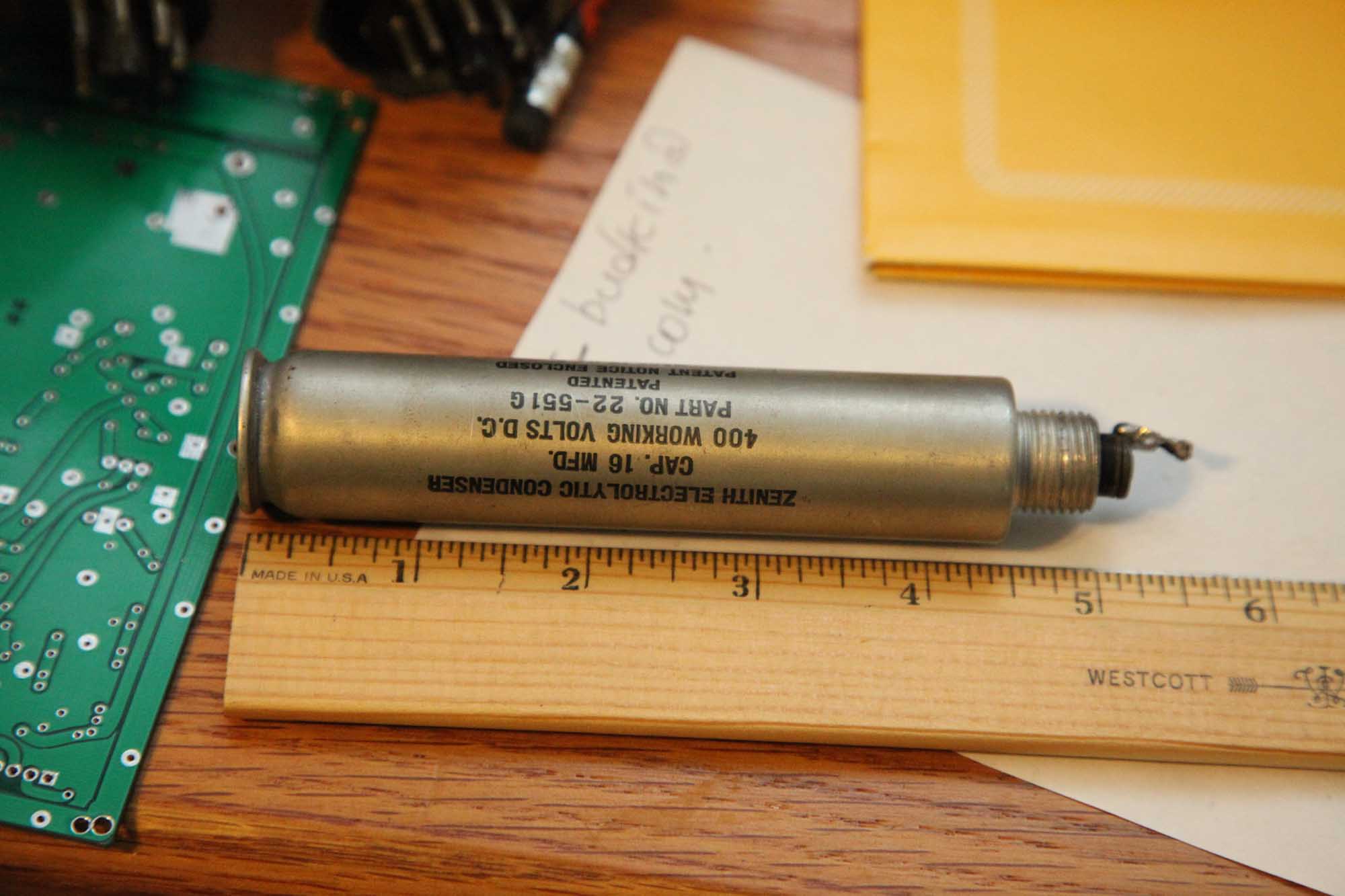
I have a Zenith electrolytic that is totally dried up (says 16uF 400V, measures at 1nF and is suspiciously lightweight), and that is very slim and long (under 1" diam. and 5.5" long).
I want to restuff it but not sure where best to cut it. I want it to look undamaged when it's done, but if I cut the top, I simply won't reach to the bottom. Too long and narrow. If I cut the bottom, it will look like you know what.
Anyone has experience dealing with those?
I had no problem with those that were twice as wide, but this one's a challenge.
PS. How do I connect the Negative wire to the aluminum body? (soldering won't work on aluminum.)
Posts: 2,128
Threads: 18
Joined: Oct 2008
City: Merrick, Long Island, NY
Don't seem to be problem replacing a modern 22 mf/450 VDC electrolytic in it's place. Just observe polarity. Forget about stuffing old one unless you are working in a museaum. Negative almost certainly would be "body" but trust the schematic and original connections.
Posts: 16,495
Threads: 573
Joined: Oct 2011
City: Jackson
State, Province, Country: NJ
Codefox,
Well, I know that, about polarity and such.
I really want this cap in this radio, and this is the sole purpose of this post.
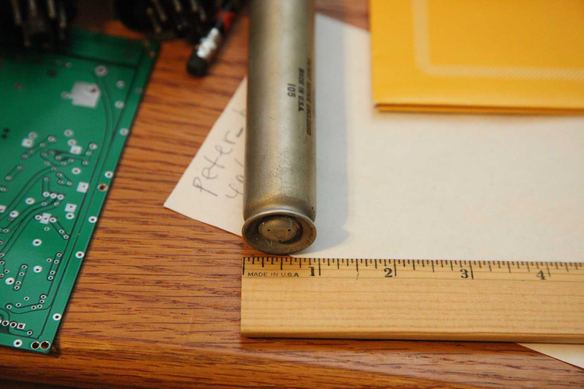
Here is the cap.
Posts: 3,152
Threads: 56
Joined: Apr 2011
City: Lexington, KY
I would first try going in from the top. Using some small long needle-nose pliers and hemostats you should be able to gut the thing and slip in the new cap and fish the leads out the bottom.
If you can't do it from the top I think if you make a thin/clean cut close to the bottom it will not look that bad when reassembled. You can find or fashion a small tube to slip both the top and bottom over and glue/epoxy them together.
I would insulate both leads and run them out the bottom and then connect the applicable one to ground under the chassis at a convenient location.
Worst case scenario would be to leave the old capacitor on the chassis and mount a new one underneath. That's the way an old repair shop would have handled it, and you could even stuff the new cap into an old axial electrolytic for a period correct looking repair. Just a couple of ideas for you to think over.
John KK4ZLF
Lexington, KY
"illegitimis non carborundum"
Posts: 16,495
Threads: 573
Joined: Oct 2011
City: Jackson
State, Province, Country: NJ
John,
Thanks, yes, the axial electrolytic is not a bad idea.....provided I can get me one of the old.
As for the two insulated wires out, you probably mean something like this?
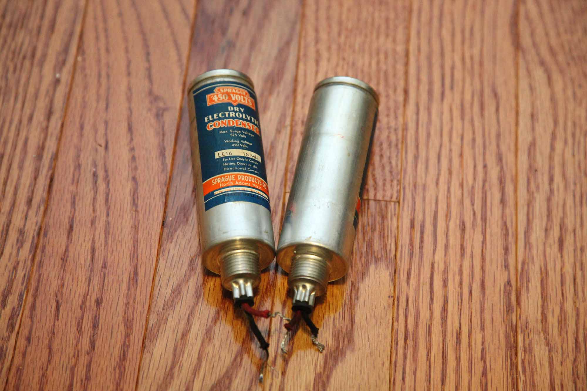
Those had insulated body and two wires and this is how i re-stuffed them; I can make this one look like it too.
Actually this is an even better idea, as the length precludes me from soldering to the center pin, but if I don't need it and am out to simply gut the cap and remove the center pin, it requires no finesse and can be done even with this length to width ratio.
Thanks, I think I know what I'll do.
It pays to discuss things.
Posts: 16,495
Threads: 573
Joined: Oct 2011
City: Jackson
State, Province, Country: NJ
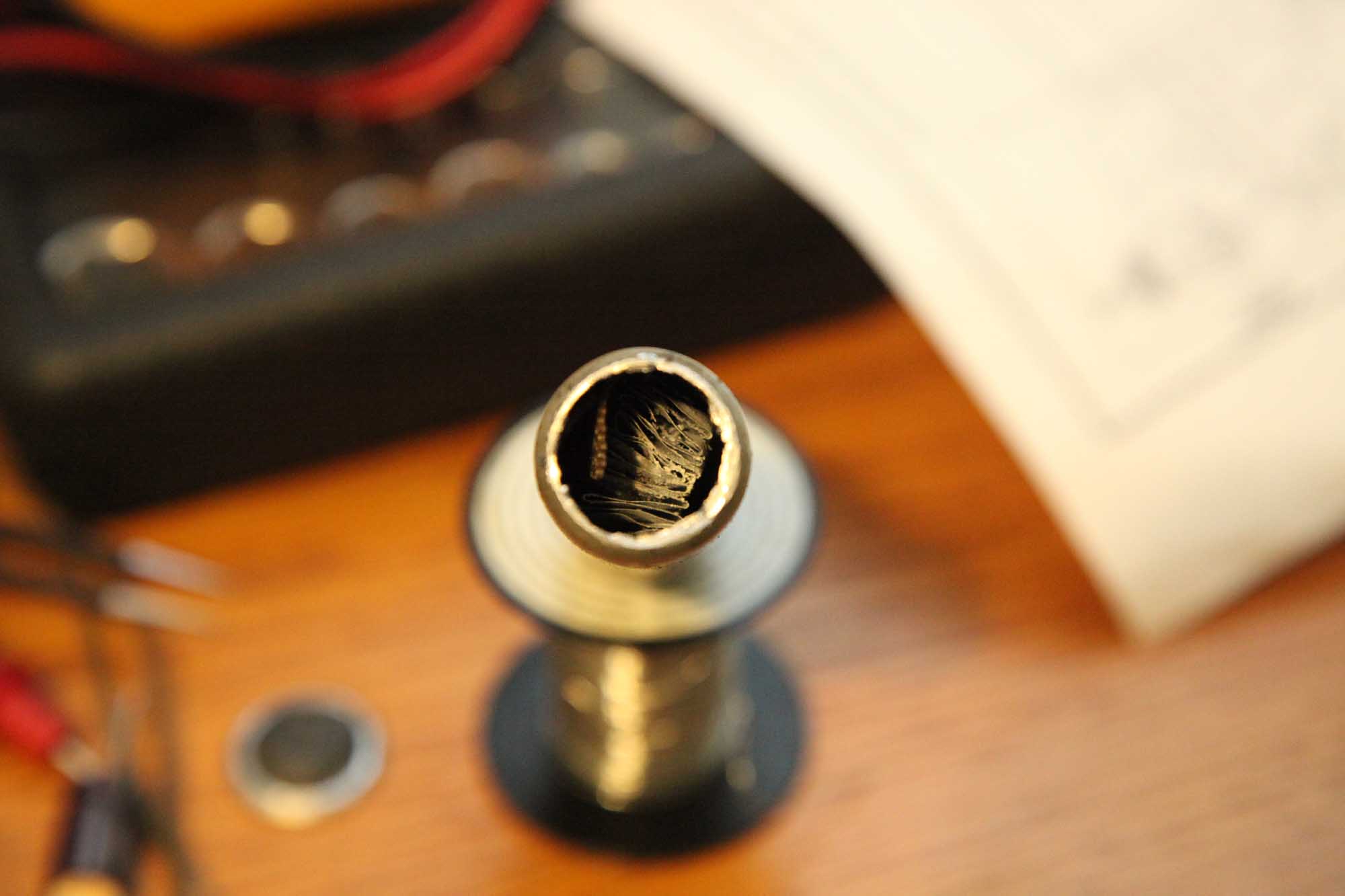
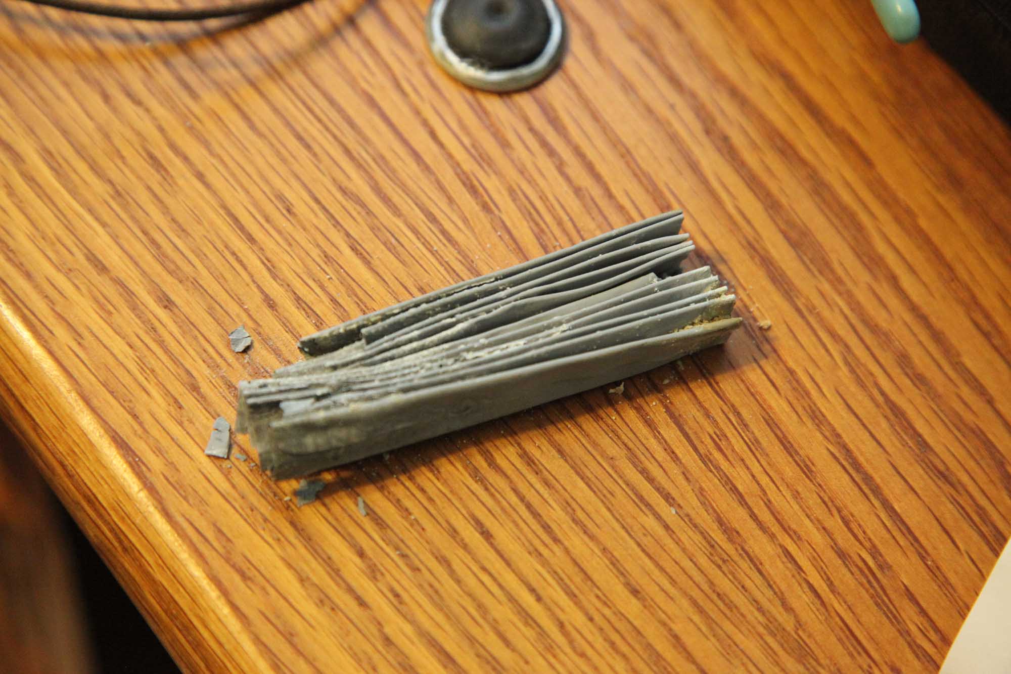
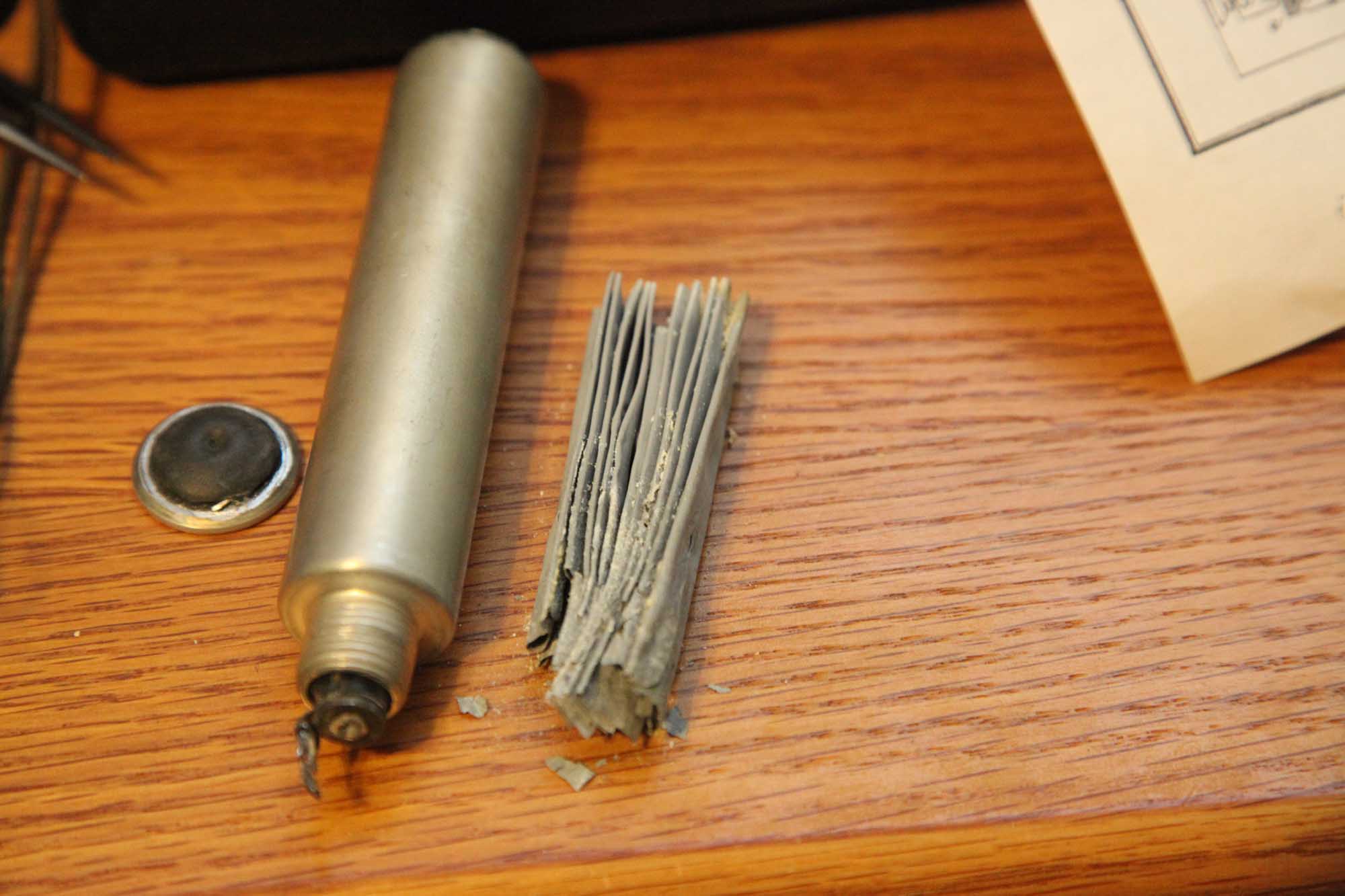
I will post photos either today or tomorrow: I cut off the top cap with my Dremel and the cutting disk, right at the groove, so it will look fine.
Insides were as dry as H**l on a hot day in June.
Taking them out did not pose any problems, and there was no tar or anything. It was dry dry.
The central rod is quite high and should it be solderable I'd have no problem soldering to it, but I think it is not, and it is attached to the solder contact with a rivet of some sort.
So as I planned, I will remove it and go with two wires.
I will wait 'till I finish, but so far it is not nearly as bad as I thought it would be.
Posts: 2,128
Threads: 18
Joined: Oct 2008
City: Merrick, Long Island, NY
Posts: 16,495
Threads: 573
Joined: Oct 2011
City: Jackson
State, Province, Country: NJ
Oh Me lave los manos, sin duda. Load of dust and who knows what else.
But then any opened electrolytic commands the same handwashing: wet or dry, it is all possibly very toxic if ingested.
PS>
Here, I made some pics.
Users browsing this thread: 1 Guest(s)
|
|
Recent Posts
|
|
Philco Model 249 made in England
|
| Gary - Thanks for responding! I hadn't actually taken possession of it at the time of my post but since you said it was...fklown — 03:32 PM |
|
Philco model 40-100
|
| Marion;
Replacing volume controls was something some service shops did in years gone by to make a little extra profit...Arran — 03:24 PM |
|
Philco Model 249 made in England
|
| Welcome to the Phorum, fklown! That's one heck of a Philco 'yardstick' you've got there! Could you possibly post a clo...GarySP — 03:19 PM |
|
Philco model 40-100
|
| Arran,
Thank you so much for your assistance and the link to the fleabay listing! They say a picture is worth a thousan...mhamby — 01:43 PM |
|
Philco Model 249 made in England
|
| I wonder if anyone has any information or experience with this model. My internet searches are coming up with nothing. ...fklown — 11:40 AM |
|
Road Trip for a Philco 46-480
|
| Good morning, folks! I’ve finished the cabinet and the electrical restoration, and have detailed those in their respecti...jrblasde — 10:56 AM |
|
Studebaker/Philco AC-2687 car radio
|
| Arran,
Thanks for checking you manuals.
I appreciate that. Let me know what you find.
PhilPdouglaski — 08:46 AM |
|
Studebaker/Philco AC-2687 car radio
|
| I have some car radio service manuals, Riders I think (not to be confused with the big blue binders), so I may see if on...Arran — 01:20 AM |
|
Philco model 40-100
|
| Greetings;
Here is an update, I found a listing on fleabay for a similar chassis to yours, and it has a photo of what...Arran — 12:58 AM |
|
Philco model 40-100
|
| Greetings;
I think I may have found a clue as to what is missing, from a search I made, there is a rear view of the c...Arran — 12:12 AM |
|
Who's Online
|
There are currently 703 online users. [Complete List]
» 2 Member(s) | 701 Guest(s)
|
|
|

|
 
|


![[-] [-]](https://philcoradio.com/phorum/images/bootbb/collapse.png)


