11-17-2012, 09:55 PM
This is the final product. It also uses paper insulator (the cap's minuses are not really GND so they are insulated) so whatever imperfections are there, they are concealed anyway.


|
My Philco 18
11-17-2012, 09:55 PM
This is the final product. It also uses paper insulator (the cap's minuses are not really GND so they are insulated) so whatever imperfections are there, they are concealed anyway.
11-19-2012, 12:35 AM
Today I was tending to the resistors. Surprisingly about 90% of them are just fine, first time I see something like this.
Now the caps. Those i have to buy. Hopefully the rest is Ok. Also realized I have mod. 124, after discovering some inconsistencies.
11-19-2012, 09:56 AM
Actually, that would be called a Code 124 chassis version.
Model numbers would go through minor and major production changes. Minor ones would be documented as "Production Change Notes." Major ones like tube type changes, parts changes/deletions that made significant schematic differences or some mechanical variation were called CODE versions. All models started out as the base model, Code 121. Usually, base models did not actually have Code 121 on the labels, although some did. No consistancy. Philco used Codes 122, 123,....up through 130, depending on the model. :-) Chuck Chuck Schwark, The Philco Repair Bench [Image: http://www.philcorepairbench.com/images/philog3tiny.gif] http://www.philcorepairbench.com
11-20-2012, 11:37 PM
I wonder why 121?
12-22-2012, 02:47 PM
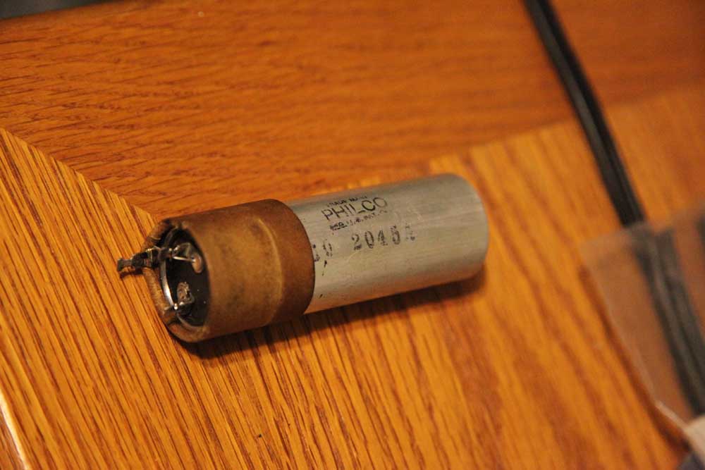
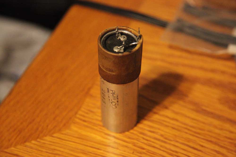
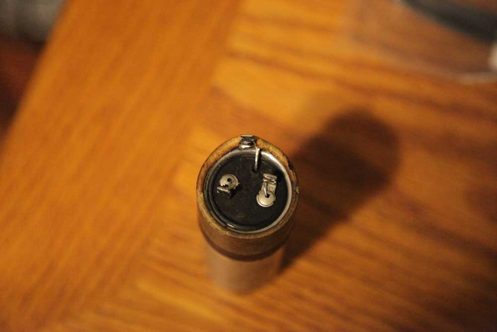
This is how I restore the backelites without taking them out and without desoldering.
A cap. Unscrew. Also, as you can see, unlike in the previous photo the wires going through the grommets are cut, so when pushing the stuffing out, nothing holds it. Heat with the Milwaukee gun. Push out the stuffing with a small Allen wrench (needs to be dull.) The stuffing is out.
12-22-2012, 02:49 PM
New cap. Put it inside and solder. Screw the whole thing back in place. Done! All takes about 10 minutes as the de-soldering is not necessary.
12-22-2012, 06:51 PM
Mortz, I agree, no reason to take wires off. I do think you might of missed one step. While the block is mounted I take a small drill that matched the hole in the grommets and with a hand drill, a couple of turns to break the wire coming through. Makes removal of the tar block much easier. I have also found that it is easier to do if you have a little room to heat the block with a heat gun at the top while the block is still mounted and then push down though the holes with something like you suggested. I use a large paper clip opened up but anything that will fit through the grommet hole will work. Then I remove the block and pull out the tar and caps. Really helps to release the cap wired before heating.
Jerry A friend in need is a pest! Bill Slee ca 1970.
12-22-2012, 08:28 PM
Yes I do cut the wires, and do it with regular cutters - the wires are so thin that it does not take much to severe them.
I did not show that since to me that was kinda obvious.....
12-22-2012, 09:00 PM
Certainly obvious to you and to me but perhaps not to a noobie.
Jerry A friend in need is a pest! Bill Slee ca 1970.
12-22-2012, 10:54 PM
I iwill edit the text
Is this better? It is quite clear there that the wires are cut, and in the first photo they are still attached.
12-22-2012, 11:31 PM
Thanks Morzh, although the pictures are great, a noobie might miss that vital part. That clarifies that step.
Jerry A friend in need is a pest! Bill Slee ca 1970.
01-19-2013, 07:04 PM
Back from vacaciones.
Necessito ayuda Now that I have just finished re-capping (I was surprised: most resistors are within 5-10% so I only had to change 6 of them that went outside 20%. None was really off. Very strange. Those ARE original Philco resistors. Anyways.) and put all tubes through the tester (most act like new) I have one last step to complete before I try to power it. My tuning cap is really loose. So I decided to look how it is secured: it is set on rubber grommets with the screws that seem to go through insulated from the chassis. However the frame of the cap shows connection to the chassis. Upon further looking I saw that fat copper braided connection that stems from under the cap #20 (I have Code 124 Philco, so here's the Rider; look at the p.3 right in the center of the assembly chassis bottom view) and then solders to the rear screw that holds the tuning cap. That obviously is the GND connection. Why then isolated screws? And is this braid soldered to actual screw cap (which is probably steel) the original way it was done? http://www.nostalgiaair.org/PagesByModel...013149.pdf
01-19-2013, 09:53 PM
Welcome back from vacation Mortzh. Those grommets are more for vibration from the speaker to the tuning cap, not for ground isolation. Some are a real treat to change out, depending on the chassis. You don't want the tuner just flopping around.
Jerry A friend in need is a pest! Bill Slee ca 1970.
01-19-2013, 11:46 PM
So this is what they are for! To stop microphoning.
Otherwise there is an easier way to connect a cap to a chassis.... Thanks Jerry.
01-20-2013, 08:55 PM
Well, it plays now. Loud, clear.
Pulls many stations on BC Band, very sensitive. First I almost killed it. Shame on me. I powered it without speaker first, all was normal, so I plugged the speaker, heard the low "boooo". measured the B+, and it was about 80V, so I pulled all the tubes, and it was still the same, so I simply measured the resistance to Chassis from the Filter choke and so it go to Zero when the speaker was plugged. I traced it to a wire that I jammed when putting a rebuilt backelite cap back. And I always watched for that, and still missed one. Well, I put two layers of heatshrink over the damaged insulation, plugged it again, measured the B+, saw it being OK, turned the volume.....voila! Praise the Lord for the Impedance and for oversize transformers! The 80 tube was starting to glow just a bit....that told me something. Now I have to: 1. Fix the wiring from the tone control: they used rubber wires and they are cracked all over. 2. Add more rubber washers under the tuning cap. I found many grommets in Lowe's, but none was high enough (there is a metal cylinder inside the grommet, so when fully compressed it has to still remain under the top of the grommet to allow compression/damping) so I used extra rubber washers...still not enough, need two more per screw. 3. Need to start looking at the shadow meter. The bulb is OK, but I don't see any action....maybe I still don't know how to operate it. 4. Replace the power cord: it seems to be OK mostly, but in one place it is damaged. I will buy some together with the speaker cloth and wiring for Tone Control. OK, well....it is moving!
« Next Oldest | Next Newest »
Users browsing this thread: 1 Guest(s) |
|

|