Restoring my 37-116. It plays now!
Posts: 16,562
Threads: 573
Joined: Oct 2011
City: Jackson
State, Province, Country: NJ
Hit a little snag...well, not so little.
I cannot 100% remember how to re-assemble the dial assembly.
That document that Ron pointed me to...well, it is for those privvy to the wisdon of Philco inner secrets. It is not really that good, it has no itemised diagram, and when thhey show a number you have to look for it in more tham one drawing, and vise versa, when they have an item on a diagram (not very readable unless you already know what's what) you have to look throughojut the text for it....does not work for me.
Also when I tried the dial I bought from RadioDaze, it does not fit the size of the hub by maybe 0.02". I tried the old hub - fits just fine.
Too anticipate the question wbout whether I bough the right dial (there are two) - yes, I bought the right one, the other is totally different. It is just a tad smaller. Not sure what to do.
I need a detailed instruction of how to put together the dial assembly, and this is not the one, at least fopr a person who never did it before.
I did put down my own diagram of what follows what, but the dial was broken in the first place so couple of steps may be missing through no fault of mine......
If anyone could point me to some detailed well-understandable set of instructions, I'd be eternally grateful.
Posts: 16,562
Threads: 573
Joined: Oct 2011
City: Jackson
State, Province, Country: NJ
OK,
Mechanically challenged though I am, I was able to assemble the dial assembly tonight.
My own diagram upon closer examination proved to be fairly accurate, the only thing that kept me from succeeding was the lack of understanding of the parts' interaction, both mechanical and electrical.
First I ground off the excess material off of the dial hub, I have to express my displeasure with the Daze's dial - it does not fit well and the material is not filed off easily - the Dremel stone barely has any effect on it, so it took me about 30 minutes of grinding and fitting, and regrinding and refitting.....
Then I also fixed the band pointer illumination disk, which was cracked and broken in several places, so I clear-taped what fell off and then used the old dials' chips to re-create missing pieces.
I also did not understand the orientation of a wide ring going between the band illumination disk and the dial. EVentually I realized the way it goes there.
Also I figured how the volume cutout switch works and after that everything was a snap.
Now it stands there on my table and I am able to operate the dial.
I may want to figure out how the preset tuning works just for the heck of it, I don't have much use for that, but would be interesting to put my local station on the auto-dial.
Now the main question - all those gaskets I have on the treble and On/Off switch shafts - where do they go?

Posts: 16,562
Threads: 573
Joined: Oct 2011
City: Jackson
State, Province, Country: NJ
So, bought weatherstripping, tossed the felt, installed the speaker.
The speaker is missing one large bolt that holds it to the bars, will have to buy it also....forgot, just went to Lowes for weatherstripping....a forgetful head makes a weary pair of heels 
Posts: 298
Threads: 22
Joined: May 2012
City: Chattanooga
State, Province, Country: TN
^^^ 
I do the same thing way too often.
It's not how bad you mess up, it's how well you can recover.
Posts: 7,305
Threads: 270
Joined: Dec 2009
City: Roslyn Pa
Would a few pics of the mounted speaker help???
Terry
Posts: 16,562
Threads: 573
Joined: Oct 2011
City: Jackson
State, Province, Country: NJ
Terry
Of course, always good to have few more pics. I have mounted it by now, as the speaker itself is not that complex an animal - there is that felt that I use the weatherstrip instead, two bolts and two screws, at least that what it was when I got mine (with one bolt missing).
It is my understanding the speaker is not mounted to the speakerboard by the rim, and is only pressed against the felt strip due to the location of the mounting holes for the bolts on that horizontal bar, am I correct?
If you could provide me with some guidance as to the grommets - it would help a lot. Not sure what goes where.
I am champing at the bit to hear it play when fully assembled.
---------
On a different note, I was pleasantly surprised to see the magnetic tuning work. It grabs at a station and holds on to it.
What I do not understand is what those 4 lamps do when the mag. tuning is engaged. Whatever they light is behind the cabinet's front panel. Of course when I put the chassis in I might see something I am not seeing now.
Posts: 7,305
Threads: 270
Joined: Dec 2009
City: Roslyn Pa
best I remember the spkr bolt to the cabinet cross brace with two 5/16 or 3/8 stove bolts. Those have a rounded head and on the back side of the head it is square. It locks into the square hole in the spkr bracket.
Grommets?? Not sure what you are talking about. There is a rubber part that fits under the chassis at the rear center( between chassis and cross brace on cabinet.
Hope this helps
Terry
Posts: 16,562
Threads: 573
Joined: Oct 2011
City: Jackson
State, Province, Country: NJ
Terry
Yes the speaker bolt (the one I have) is with the round head and sqare neck and it gets locked in the square hole (I guiess they used a square drill bit, huh?) - I will need to buy the second one.
The rubber part - yes I am talking about those that fit between the chassis and the crossbar.
I am not sure how many of them go there, there are also no through holes in the crossbar where those round mill-outs are. (they remind a fig. 8 - two intersecting circles).
But there a severall various rubber parts - some of them are obviously too big to fit in between teh chassis and the crossbar.
I can take a pic.
Posts: 7,305
Threads: 270
Joined: Dec 2009
City: Roslyn Pa
Here's a couple of pics I had on file of the '116 std.The deluxe was missing the hardware so I had to make the wooden pieces to mount it.
http://www.flickr.com/photos/53710524@N0...otostream/
http://www.flickr.com/photos/53710524@N0...otostream/
Terry
ps you might have to look around as it didn't capture the pics I clicked on
(This post was last modified: 09-02-2013, 08:49 PM by Radioroslyn.)
Posts: 16,562
Threads: 573
Joined: Oct 2011
City: Jackson
State, Province, Country: NJ
thanks Terry.
I guess I will have to post the pics of the pieces I have in mind.
Let me do just that.
Mike.
Posts: 1,106
Threads: 88
Joined: Jun 2011
City: Tacoma
State, Province, Country: Washington
If I hadn't seen one with my own two eyes, I would never have believed there were such things as square drill bits. I'm STILL not sure how they work. (o)o)
Posts: 16,562
Threads: 573
Joined: Oct 2011
City: Jackson
State, Province, Country: NJ
Brenda
The drill bit is a so-called Reuleaux triangle and if mounted in a special way that allows it to rotate off center it can make a hole that is practically square with minimally rounded corners. Looks linda like the rotor in Vankel engine except it is a bit different.
Posts: 16,562
Threads: 573
Joined: Oct 2011
City: Jackson
State, Province, Country: NJ
Here are some photos.
Rubber grommets or whatever you call them plus one pic of the speaker mounted.
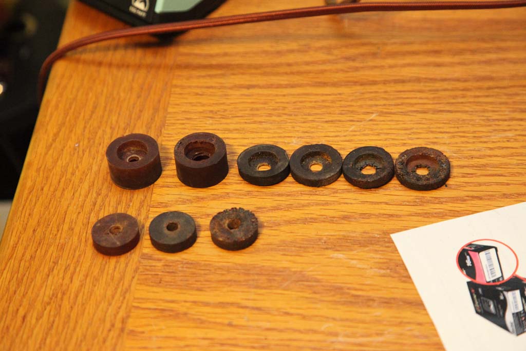
All grommets
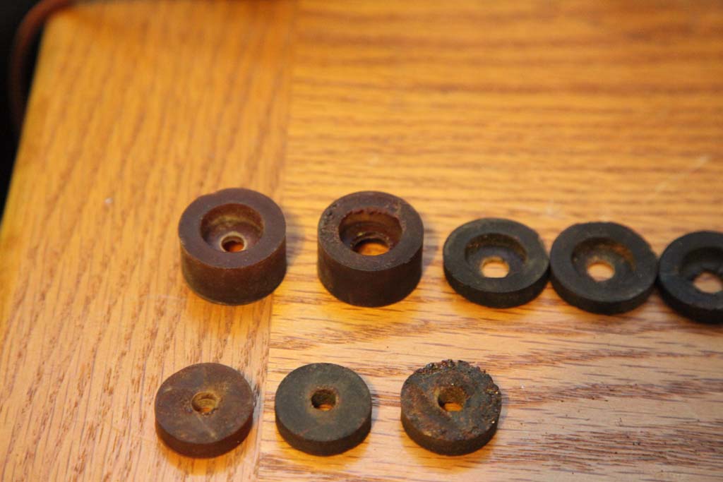
Closeup 1
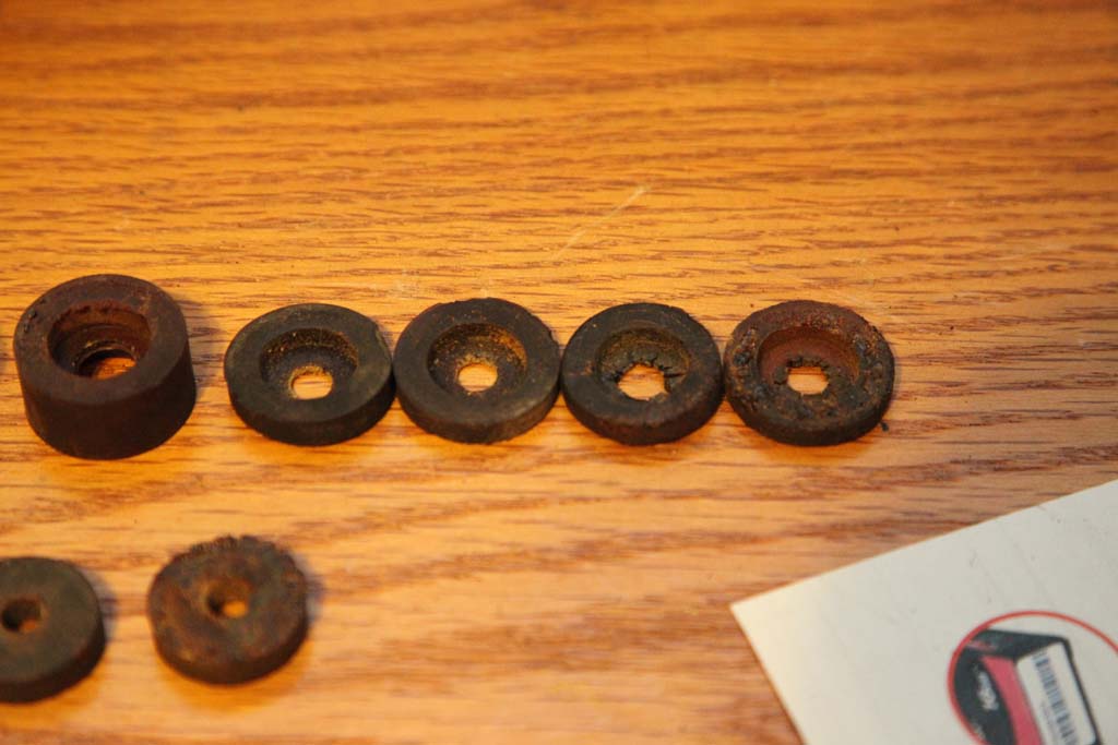
Closeup 2
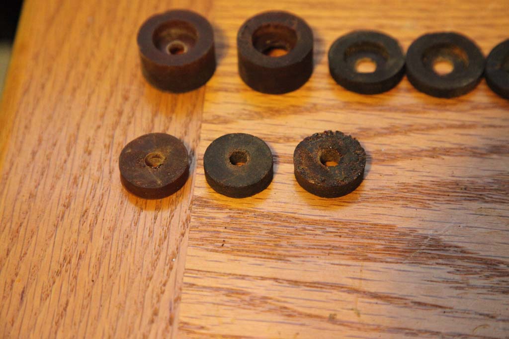
Closeup3
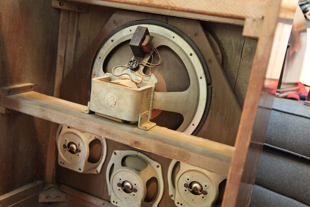
Speaker
Posts: 761
Threads: 56
Joined: Jul 2013
City: Kentucky
Morzh, I've never worked with your model, so keep in mind that I could be wrong. I think the two thick bushings probably go on the front of the chassis. Look for two metal posts sticking out on each side of the front of the chassis, and two holes in the cabinet. They cushion the front of the chassis up against the cabinet. The three smaller ones are for mounting the chassis. There should be holes in the board the chassis sits on. There should be four of them and the missing one may well be stuck in the cabinet. The other four, I am not sure about.
I am sure someone will speak up who knows for sure, but maybe my info will get you started.
The artist formerly known as Puhpow! 8)
Posts: 16,562
Threads: 573
Joined: Oct 2011
City: Jackson
State, Province, Country: NJ
PuhPow
You are probably right.
I am not sure about the big ones - the holes seem to be a bit larger than those posts but could be still.
Both smaller and larger flatter ones fit in those mill-outs under the chassis, in the board, so they are probably to cushion the chassis. Why they need the holes...not sure, there are no through screws that go there as there are no through holes drilled, so it is just padding then and the screws go separately in some other place. I guess they did cushion the heck out of that chassis.....it's a heavy one.
Users browsing this thread:
|
|
Recent Posts
|
|
HiFi (Chifi) tube amp build - but my own design.
|
| Well, maybe - maybe not :lol: It's been an interesting project so far! Something so simple, yet so cranky. The 1st one ...TV MAN — 05:12 PM |
|
1949 Motorola 5A9M
|
| Haven't thought of Burgess batteres in a while
https://www.radionostalgia.ca/lib/Images/battery/us/burgess1D.jpgi
...Vlad95 — 03:50 PM |
|
Philco Model 16 wiring question
|
| Measure the voltages first, just in case.morzh — 02:19 PM |
|
1949 Motorola 5A9M
|
| Haven't thought of Burgess batteries in a while Mr. Fixer. Boston Edison always used Burgess in their Bright Star yellow...Paul Philco322 — 02:17 PM |
|
1949 Motorola 5A9M
|
| Thanks Sam. I'll let you know. I can probably scare some up from the local radio club.klondike98 — 02:07 PM |
|
Philco 89 Code 123 Osc Coil
|
| Hello,
I thought I would post my findings on my bad oscillator tickler coil. There were 27 turns on the outer coil b...dconant — 12:38 PM |
|
Philco Model 16 wiring question
|
| Thanks Morzh. So it appears I did wire it incorrectly and I have to switch the wires between pins 2 and 4.bobclausen — 09:24 AM |
|
Philco 46-1209 strange behavior
|
| No, it's not a problem, just during certain condition it could show up.
Yes, an internal tube short could do that too.
...morzh — 09:13 AM |
|
HiFi (Chifi) tube amp build - but my own design.
|
| You sound guys are never satisfied. :crazy: :clap:RodB — 09:10 AM |
|
HiFi (Chifi) tube amp build - but my own design.
|
| I got some new ceramic octal tube sockets installed and also tried some different coupling caps.
The results:
The go...TV MAN — 08:42 AM |
|
Who's Online
|
There are currently 1325 online users. [Complete List]
» 3 Member(s) | 1322 Guest(s)
|
|
|

|
 
|


![[-] [-]](https://philcoradio.com/phorum/images/bootbb/collapse.png)


