Posts: 10
Threads: 1
Joined: Aug 2013
City: Dowagiac, Mi.
I just measured my original Philco 4990 mica caps, they are both marked with yel.-gn. dots and they are approx. 35pf in value. Also part #17 does not connect directly to gd. but to pin #4 of the #24 tube exactly where part #22, the other 35pf cap connects. If you look on the Philco mica caps parts list, #4990 is listed as a 35pf cap. with yellow and green dots. I really can't tell if the small choke was factory or not.
Good luck with your project- I can confirm that both sch. available are filled with errors and I really had my doubts when I fired mine up- but it works good.
Posts: 16,481
Threads: 573
Joined: Oct 2011
City: Jackson
State, Province, Country: NJ
Scott, thanks.
So Chuck's specs were correct all along. 35pF.
In my radio as I said only one is left and I cannot be sure that is factory. And it is marked only on one side with a large yellowish-greenish smeared dot, and not in one of those indented round places where the color dots usually go.
I will measure it soon.
As for the connection to the cathode instead of GND, I do not think it matters much, like in 70 in the same exact arrangement in the pi filter both caps go to Ground. But of course I will make it the way the sch is now.
OK, we are making progress!!!!
Posts: 16,481
Threads: 573
Joined: Oct 2011
City: Jackson
State, Province, Country: NJ
At least something was easy; the fortune smiled at me tonight: the backelites were a snap to re-stuff. They barely needed heating and the contents snapped out readily with minimum of chipping of the tar and such.
Also I discovered an easier way of pushing out the potted contents out of the backelite shell: I leave the cap in place without unscrewing it first. (of course I bite off the wires). Then, provided I have the space around it, I heat it with a milwaukee gun on one side, and I keep the gun on Low for 10 sec, giving it a 2-3 sec Hi blast, and then repeat it with the opposite side. I think keeping it Low would also work. Hi is useful if there are no sensitive parts close to the cap that could burn/melt.
Then without unscrewing the cap I push the Allen wrench of the thickest possible gauge that fits through the central rivet inside and push out the contents.
Then I unscrew the cap, turn it and pull the contents out.
Why?
Well, for starters, when you heat the cap, you have to hold it with your fingers and that may be somewhat uncomfortable as it may be fairly hot.
Second you have to hold it tight with your fingers and provide the resistance to the push of the allen wrench with your hand and it is usually somewhat slippery due to the old grime and skin oils and all other stuff.
If however it is still screwed in place you do not need to hold it, burn your fingers and flex your muscles - you simply push the wrench (or what have you) 'till it snaps out.
One thing though - it works because the caps I have have the bushing through which the screw goes raised relative to the potted surface, so the potted block has the space to come out. If for whatever reason there are such caps without this feature and the potted surface is flat against the chassis, it won't work. I am not sure if such caps exist or it is a product of my false memories.....
Posts: 4,864
Threads: 54
Joined: Sep 2008
City: Sandwick, BC, CA
I believe that you are right Mike, it's been a while since I restuffed a Philco Bakelite block, but the ones I remember handling had a built in stand off of about 1/8 of an inch or so above the chassis. I did this the hard way, I disconnected everything, removed each block, melted out the contents with a heat gun, and then restuffed it, but if you can do it in place so much the better. I could see this working quite well since they likely focused on potting the bottom portion of the block more so then the top, unfortunately I don't think my heat gun has that level of control, it just has a high and a low setting.
Regards
Arran
Posts: 16,481
Threads: 573
Joined: Oct 2011
City: Jackson
State, Province, Country: NJ
Arran
mine is a 20-bucks Milwauke, and also has Hi/Lo and nothing in between. Should work fine. Low should be enough.
The first ever done by me were in my Lowboy 20 and I also did it the hard way, disconnecting, taking it down to the garage, heating, pushing and restuffing. Then I realize just unscrewing and turning would be enough in most cases. And now I'realized no manipulation is needed to push the contents out; eventually you will have to unscrew and turn but you won't have to hold it and apply force.
Well, all comes with experience 
As for the heatsource, I even think a hairdryer fan would be enough.
Posts: 16,481
Threads: 573
Joined: Oct 2011
City: Jackson
State, Province, Country: NJ
Scott, one more question:
On my chassis the tin-box caps are #25 and 28, a double (a thinner one with two wires) and triple (a fatter box with three wres) are installed as follows:
The #25 double is on the wall, and #28 triple is at the main chassis panel.
I think the chassis drawing shows otherwise - the fat triple should be on the wall and the slimmer double should be at the panel.
Can you tell me what your arrangement is?
I've just rebuilt both (was pretty simple plus I have rebuild at least two chassis containing those so I have now the procedure developed for that) and am looking to installing them back tomorrow. There are no problem installing them either way and I do not think it will affect anything, I simply want the chassis to look as close to original as possible. Someone did rearrange things while trying to fix it.
Posts: 16,481
Threads: 573
Joined: Oct 2011
City: Jackson
State, Province, Country: NJ
While connecting the rebuilt metal box caps I measured the only mica cap I have out of the two that were in question in the sch, #22 (those whose values were changed to 35pF).
Mine is 350pF.
I do not know what to make of it as the radio was obviously "fixed" before and it is kinda obvious so I would not use this as a reference, and again, the LC filter was missing.
I've decided to keep it and build the filter after it.
Now another boo-boo: in the very beginning I could not understand why the connection point of resistors 23, 23 and 28 is also connected to he speaker socket. The peaker point happened to be "E" voltage. Now I get it - whoever fixed the chassis decided to save one cap ad use the one that decoupled "E" to also filter the detector plate voltage. Wow, what a thinkin'. I wonde how it worked although I have a theory.
I also suspect I know why the LC filter was done waya with - the inductor likely burned for whatever reason and so they decided "heck with it, we'll get away with a single cap across". Which is not to say it would not work....
Now I have to be careful and check to see if there is a short in the tube.
Posts: 10
Threads: 1
Joined: Aug 2013
City: Dowagiac, Mi.
Morzh:
Yes, My tin box caps, #s 25 and 28 are reversed just like you found yours. The 25 is on the wall and the 28 is on the chassis. Also, to reiterate, the 17 and 22 mica condensers are of the solder tab types and are marked with splotchy green yellow paint and measured 35pf using my cap.meter which is very accurate when checking purchased caps before I install them. These appear to be original Philco parts and are listed as part 4990 on the Philco mica cap.list of condenser numbers and values available on this web site. I'll be happy to answer any other questions you might have that I can help you with.
Posts: 16,481
Threads: 573
Joined: Oct 2011
City: Jackson
State, Province, Country: NJ
Thanks, Scott.
Well, my chassis had been messed with quite a bit. It's a good thing it was not "re-designed" like someone had it here not so long ago.....
Will see. I hope to finish major works end of this week and then I will have to see what the story is with the speaker and if it had given the previous "repairman" a reason to do what he did with the chassis (though I absolutely would not do that).
Posts: 16,481
Threads: 573
Joined: Oct 2011
City: Jackson
State, Province, Country: NJ
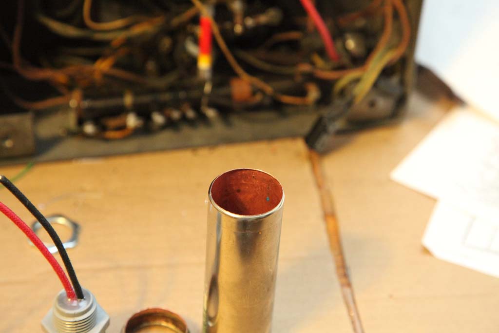
A practical question: I am rebuilding electrolytics now.
One of those is a guy with the body of a nickel-plated copper (or so it looks) and not an aluminum; the peculiarity of it is, it has a large diameter thread to bolt to chassis and it is some sort of backelite or thermoplastic, and a thick aluminum rod going through it with a thread for the electrical contact is somehow backed into that plastic.
The thermoplastic started crumbling before and when I tried to dislodge the rod a piece of plastic cracked and came of, and the rod itself eventually broke.
Now I am trying to work from inside but to no avail, it is extremely intransigent contraption.
If I choose to get rid of plastic altogether I lose the remainder of the thread that goes through the chassis so I won'ot be able to bolt the cap.
I though of mounting a clamp to the chassis that would hold the cap but there seems to be no space for it.
Any ideas? Anyone encountered these caps before to know what to do with them?
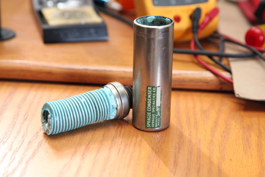
PS. Oh, I photographed the internals of that cap before I discarded it, they are beautiful - a spiral fully covered with some copper salt (it was all blue), looks like something from an alien movie. The cap was fully dried.
Posts: 16,481
Threads: 573
Joined: Oct 2011
City: Jackson
State, Province, Country: NJ
OK, seems like I figured what to do with it.
I was not sure whether I keep the insulator and this was "ce qui cause mon tourment".
Did not want to break it.
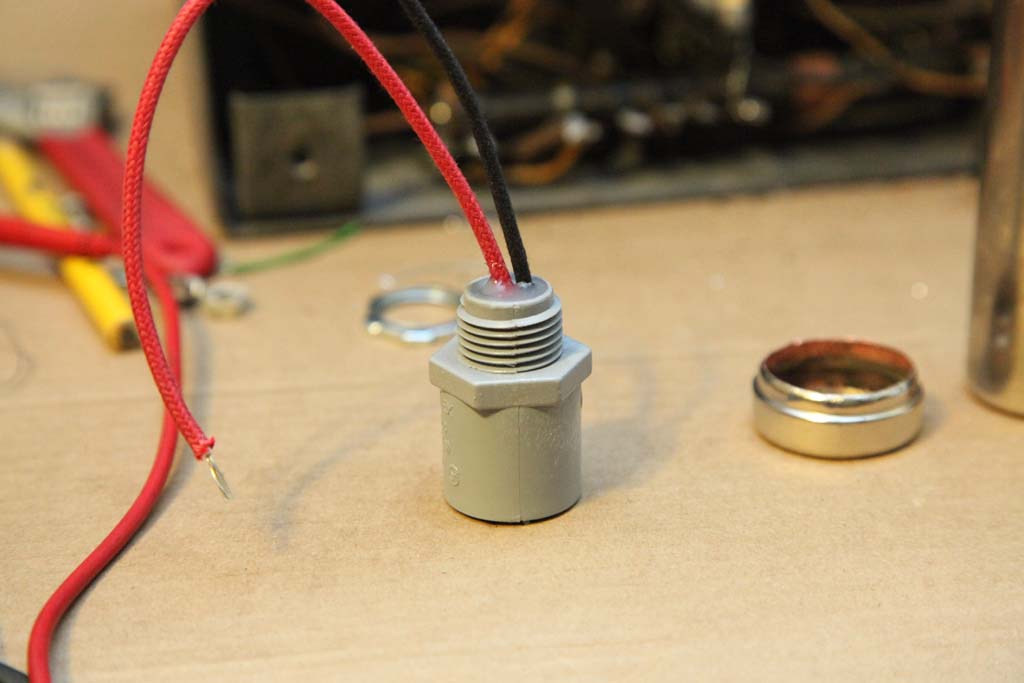
So I went to Lowes and found a snuggly fitting 1/2" plastic electrical male fitting and a locking nut for it, so this will serve as the new central insulator.
I hammered out the central rod with a nail set, it came out after a while. Then I used various barbaric methods to vrush the thermoplastic insulator. I thought it would be brittle, the piece of therad having separated and all, but boy was I wrong! Anyways, after 30 minutes of a qualm of ingenuity using all kinds of contraption I was able to crush the plastic without mangling the metal bottom much.
Then as I mentioned all was covered with blue crystals inside and the hot water did not do the trick. I was reluctant to use Naval Jelly which I think would to the trick but I was not sure what it would do to the finish if it gets there.
So, I went on a hunch. I took a large plastic jar, put the cylinder at the bottom andpoured it over with white vinegar which I have galore - it goes a dollar a gallon.
In 10 minutes the vinegar went blue and the crystals were mostly gone.
I rinsed the tube, and then ashed it in baking soda solution to stop the acid.
Rinsed well again and then baked it at 200F for 20 minutes.
Now it is ready to receive the new capacitive innyrds and be fitted with the new insulator and potted.
And all this was done while fighting my frozen pool pump - did not start it yesterday and by the time it started it froze, and then teh breaker tripped. had to disassemble the whole piping, flush the ice out.....fun.
Posts: 16,481
Threads: 573
Joined: Oct 2011
City: Jackson
State, Province, Country: NJ
Here are some pics of fixing tone control and that electrolytic cap.
Tone control.
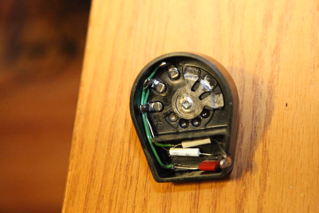
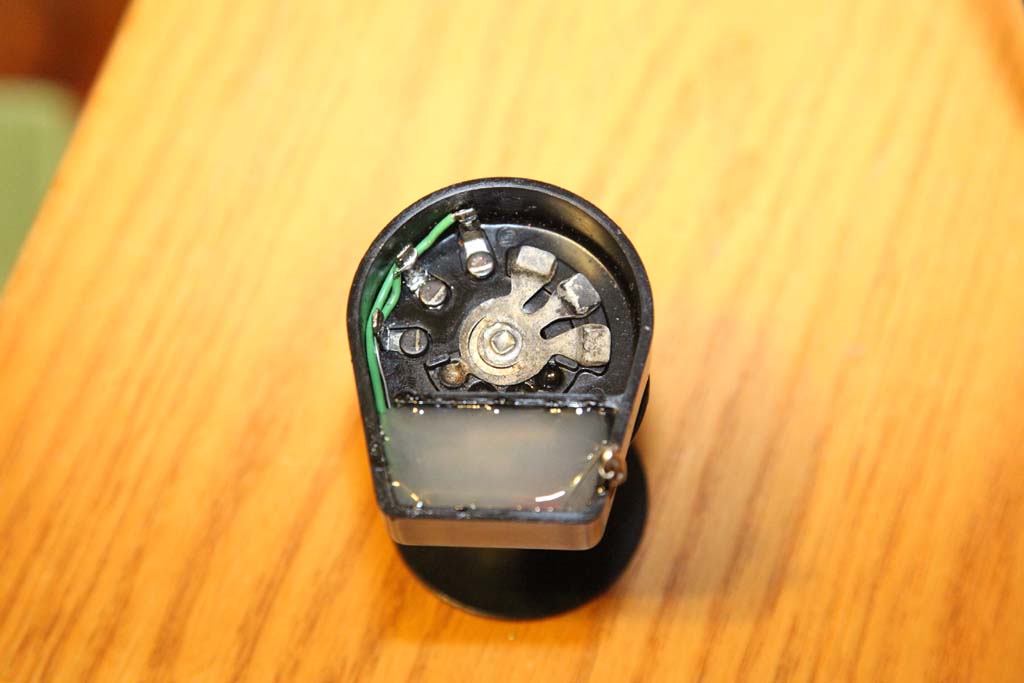
The cap, fresh opened.
Stuffed and potted male 1/2" fitting
Cleaned shell.
Posts: 16,481
Threads: 573
Joined: Oct 2011
City: Jackson
State, Province, Country: NJ
Posts: 157
Threads: 7
Joined: Feb 2013
City: Osceola, IN
Mike,
Very nice solution to a difficult cap rebuild! I haven't come across one of these yet, but I'll keep this fix in mind for the future.
Posts: 1,106
Threads: 88
Joined: Jun 2011
City: Tacoma
State, Province, Country: Washington
Some darn nice work. I especially like the way you did the tone control. I generally just run the capacitor wires directly to the connections. Your way looks nicer.
Users browsing this thread: 1 Guest(s)
|
|
Recent Posts
|
|
Refinishing Ideas
|
| Hi Poulsbobl,
I think that you could get away with it. In the Philco Library, there is a parts listand specs for sp...MrFixr55 — 11:54 PM |
|
Philco 46-480 Electronic Restoration
|
| The sleeving for the transformer arrived early, so I went ahead and finished reassembling. The chassis looks far better ...jrblasde — 10:15 PM |
|
Philco 610B oscillator wiring
|
| I don't know what you are referring to when you say "tube cathode ground". Ground is a connection to the chass...RodB — 05:56 PM |
|
Zenith H725
|
| Good points, Arran. I haven't encountered this problem with any other radio (all earlier vintages), so am learning here....EdHolland — 05:32 PM |
|
Zenith H725
|
| Ed;
One thing that I will say about these is that Brand Z was considerate enough to make these mica caps easily acces...Arran — 02:34 PM |
|
Philco 610B oscillator wiring
|
| Do you know what run # your chassis is?
It took me a while to find what you were basing updates/modification on as I did...Radioroslyn — 07:34 AM |
|
Need to purchase some accessories for restoration of my Old Philco Radio
|
| COLLEAGUES,
Thank you all for such good and important suggestions as how to find good replacement parts. I will go fo...palonso — 07:05 AM |
|
Zenith H725
|
| Here's what the inside of AM IFT2 looked like, and the other pic shows the discs I made to take place of the mica and ke...EdHolland — 07:40 PM |
|
Zenith H725
|
| IF2 will need replacement caps. The arcing was severe enough that the mica is pitted and holed where the HT flashed over...EdHolland — 04:04 PM |
|
My Philco 37-116 Restore
|
| Measuring from center tap like the tube voltages show. Cap 127 is isolated from ground. Cap 127 shown in upper left of p...dconant — 08:05 AM |
|
Who's Online
|
There are currently 952 online users. [Complete List]
» 2 Member(s) | 950 Guest(s)
|
|
|

|
 
|


![[-] [-]](https://philcoradio.com/phorum/images/bootbb/collapse.png)


