where! 3 and 4 lead caps.
Posts: 4,106
Threads: 310
Joined: Nov 2013
City: Kings Park NY
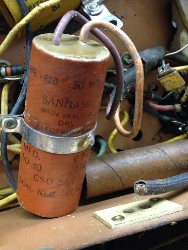
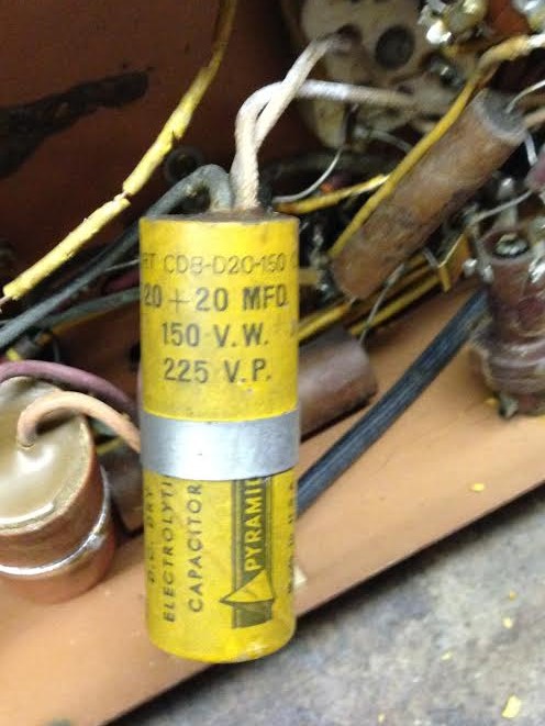
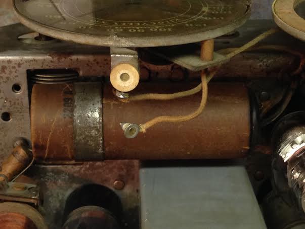
I need to buy 3 and 4 lead Ecaps and I cant locate them. One is a 20 + 20 with 2 leads out each end. The 2 right side leads do go to the same pin so I would only need a 3 lead Ecap. Another is a 50+30 with 2 leads out one end and one out the other. again 2 leads go to the same terminal so can I just use a axial standard Ecap? The next is a 20+20 3 lead radial. again 2 leads go to the same terminal. Where can I get these caps? not justradios, not radiodaze,? or at least I could not find them. Mouser is too complicated for me also.lol
Here are some pics:


Lastly, there is no way to figure out the value of a cap without a label or schematic right? I have an Halson that does no exist yet but I have 2 large caps, Ecaps I believe numbered 2209A mounted on top of the chassis and 2209B underneath. Any thoughts?
Pic below:

Kirk L
Posts: 761
Threads: 56
Joined: Jul 2013
City: Kentucky
You just use regular 2 lead (positive and negative) electrolytic capacitors to replace those. If you see a cap with three or four leads, then it is a multicap.. In other words, it is two or more electrolytics combined into one. You replace each one with an individual capacitor. Generally speaking, if there are three leads, you've got two caps that share a common negative. That yellow one in the second picture - you would replace that with two 20mfd caps. The black wire is likely negative for both.
The artist formerly known as Puhpow! 8)
(This post was last modified: 01-17-2014, 06:22 PM by Jamie.)
Posts: 1,106
Threads: 88
Joined: Jun 2011
City: Tacoma
State, Province, Country: Washington
What model radio is this (not the Halson)? I don't believe that either of those caps belong there, they look like replacements and are likely the wrong values anyway.
Posts: 16,582
Threads: 574
Joined: Oct 2011
City: Jackson
State, Province, Country: NJ
Kirk
These are potted caps, Gosh knows they still might be within specs capacitance-wise.
I just did it, so if you measure that the capacitance is what it should be, you could try to reform them, and then maybe you won't have to buy the new ones.
of course if they are dry or shorted or extremely leaky.....
Posts: 4,106
Threads: 310
Joined: Nov 2013
City: Kings Park NY
Yes Brenda,
They are replacements, They were spliced in, not even soldered. One is supposed to be 100mfd and the other should be a 30.
For the 20 + 20 with 2 leads out each end. I would get 2 20 mfd caps and and just twist one ends leads together and run the other 2 to their separate terminals and pins?
Thanks for the help
Kirk
Posts: 761
Threads: 56
Joined: Jul 2013
City: Kentucky
Yes, you would just hook up both negative leads together. But, if the schematic calls for 100mfd and 30mfd, then follow the schematic. You will find all sorts of replacement parts in old radios. People used whatever they had, especially during the war. Always follow the schematic and check it before you replace anything.
The artist formerly known as Puhpow! 8)
(This post was last modified: 01-17-2014, 09:27 PM by Jamie.)
Posts: 1,222
Threads: 86
Joined: Jan 2014
City: Annapolis, IL
State, Province, Country: USA
AES (Antique Electronic Supply) has a few "firecrackers" if you want to keep it similar to what is there. I saw a 47/80 @ 160v which would be close, bout 8.50 + s&h. There are others out there if you look around.
Tim
Posts: 1,106
Threads: 88
Joined: Jun 2011
City: Tacoma
State, Province, Country: Washington
My point is, given that this radio looks to be a late 30's style, that the caps that are in there are way too large for the circuit. I'm thinking that the originals were closer to 8 and 16 uf, and that 120uf total capacitance is going to be much, much too much. Of course, all I have to go by are the pics, and from what I can tell with those is that the radio is similar to one of the Plant A units, with 25Z5, 6D6, etc..
Posts: 4,106
Threads: 310
Joined: Nov 2013
City: Kings Park NY
You misunderstood the values, sorry i was not clear, one is a 30 in the schematics and the other is only a 50/30 and a 100 in the schematics.
But I totally understand what you are saying. I wish no one had touched it but I am getting the hang of this slowly.
Thanks for the info everybody
Kirk L
(This post was last modified: 01-18-2014, 11:05 AM by OldRestorer.)
Posts: 2,128
Threads: 18
Joined: Oct 2008
City: Merrick, Long Island, NY
Use diecrete components, just order 400 VDC replacements, they are tiny and no worry about limits. Do not bridge old components, cut them out and discard them. Replace with values equal or just above original capacitance values.
Big useful list of vendors here:
http://antiqueradios.com/forums/viewtopi...9&t=201537, hobbiest friendly site also here: http://www.justradios.com/
Bear in mind that you should also replace all the paper or wax type capacitors at the same time for a start, and you might find it prudent to replace old carbon resistors as well.
Posts: 4,106
Threads: 310
Joined: Nov 2013
City: Kings Park NY
Hey,
I am replacing all the caps in all 5 radios and have tested 90% of the resistors. One actually crumbled when I touched it.
Thanks for the info
Kirk
Users browsing this thread: 1 Guest(s)
|
|
Recent Posts
|
|
Philco Model 38-7: what caps & resistors do fail typically?
|
| Since you stated earlier, you have a console 38-7XX. They also had a 38-7T (table), and 38-7CS (chairside). A very nic...GarySP — 01:18 PM |
|
Part numbers to model cross
|
| That I wouldn't know, but sometimes the radio document itself shows one, same as the capacitor cans' etc pinouts.morzh — 12:46 PM |
|
Part numbers to model cross
|
| Thank you morzh, that is exactly what I was looking for. Now , is there some where that shows pinouts for Philco power ...Jim Dutridge — 11:37 AM |
|
Restoration of the Canadian General Electric A-87
|
| Thanks for your help Michael. In fact, this video is only an intermediate result. Later I had to apply another tinting l...RadioSvit — 09:01 AM |
|
Restoration of the Canadian General Electric A-87
|
| Great job on the cabinet.
PS. In the US notation, "kenotron" refers to specific type of tubes; we call re...morzh — 08:24 AM |
|
Part numbers to model cross
|
|
This document has at least some tables of models and parts used.
Example: Choke 32-7572, used in 604 radio.
Search f...morzh — 08:19 AM |
|
Restoration of the Canadian General Electric A-87
|
| I also checked all the radio tubes on my Hickok 530 tube tester. The 5Z3 kenotron turned out to be faulty, all the other...RadioSvit — 08:02 AM |
|
Restoration of the Canadian General Electric A-87
|
|
Well... While the varnish is drying up, I started repairing the chassis...
Of course I started by replacing the pa...RadioSvit — 07:12 AM |
|
Philco Model 38-7: what caps & resistors do fail typically?
|
| Hello Martin,
Welcome aboard our little community what great Model 38-7
Sincerely Richardradiorich — 12:30 AM |
|
Philco Model 38-7: what caps & resistors do fail typically?
|
| Welcome to the Phorum Martin.
I count about 9 paper caps, the 3 electrolytic caps and 2-Y2 safety caps to replace th...RodB — 09:44 PM |
|
Who's Online
|
There are currently 1274 online users. [Complete List]
» 1 Member(s) | 1273 Guest(s)
|
|
|

|
 
|


![[-] [-]](https://philcoradio.com/phorum/images/bootbb/collapse.png)


