Philco 70 restoration attempt - singing now.
Posts: 15,811
Threads: 553
Joined: Oct 2011
City: Jackson, NJ
Today took the 90 off the bench and fetched the 70 I acquired during the Kutztown event this fall.
Terry encouraged me to get it when I was in doubt.
Well, Terry, this one will require a good cleaning first.
And the cabinet as you remember suffers from separation of the bottom plywood (in addition to everything it was sitting on wet grass) and some dry rot of the same plywood. I think it will have to get replaced.
Also that cut off corner that will need to be manufactured and installed (and toned/laquered...etc...not my forte....nope!)
Now the chassis needs a good cleaning, some rust spots tended to, etc.
Power chord has to go...it is really rigid. And the plug is bad, but then it is not original Philco plug either so screw it.
Good news is, the speaker cloth is good, the speaker itself passes at least electrically (otherwise right now cannot test it) - both field and primary SE.
The bottom of the chassis and insides of the cabinet are sprinkled over with some copbweb mixed with what seems to be broomcorn seeds. I was afraid they were pre-digested seeds but then I did not see mouse poop anywhere which is good, but then this Philco certainly came from a barn....broomcorn barn? Or millet barn? WHo knows.
The radio was obviously repaired in a very remote past, the chord is patched and black-taped inside the chassis, the tubes are not original, none of them is.
So, the chassis is on the bench, the first order of the day is RECAP!!!!!!!!
Here we go!
(This post was last modified: 02-13-2014, 09:49 PM by morzh.)
Posts: 4,109
Threads: 310
Joined: Nov 2013
City: Kings Park NY
If you need help with the recap I know a guy. 
Times I have been electrocuted in 2021
As of 1/01/2021
AC: 4 DC: 1
Last year: 6
Posts: 15,811
Threads: 553
Joined: Oct 2011
City: Jackson, NJ
Let me guess...he is from NJ. 
Posts: 15,811
Threads: 553
Joined: Oct 2011
City: Jackson, NJ
While listening to Tubetalk went through the coils.
The primary of the 1st RF's output transformer is open.
Me no likie coil rewind.....me likie coil conduct....oh, crap.
Posts: 15,811
Threads: 553
Joined: Oct 2011
City: Jackson, NJ
Yes the winding is open for a good reason - the primary was fully stripped of enamel and when I started unwinding it it started fallin apart and the first three turns were in pieces, thereafter the wire held but was in poor shape.
The secondary is in good shape, the enamel is intact.
Tomorrow I will rewind it - I have the wire ever after I did that Emerson restoration.
OK, the first pancake is always scrambled as the national saying goes.
Posts: 16
Threads: 2
Joined: Jan 2014
City: Newmarket Ontario, Canada
Is it difficult to re wind coils?
Posts: 599
Threads: 24
Joined: Jan 2014
City: Edmonton AB CA
No not difficult but you have to pay attention to direction the wire is wound on to the form and the number of turns and the position it is in on the form. The hardest part I find is handling that really fine wire and being careful not to break it half way though. lucky thing for me here is the only coils I have ever seen that were bad were on radios from areas other than western Canada. I have never seen a bad coil on a radio from this area, think that has to do with the fact that it is very dry here and we never get any really hot temps here in the summer.
Gregb
Gregb
Posts: 15,811
Threads: 553
Joined: Oct 2011
City: Jackson, NJ
No it was not difficult at all. I probably spent more time extracting the coil than rewinding it.
Rewinding took me maybe 15 minutes.
This is one-layer coil and I happened to have matching gauge wire so there were no problem with fitting the winding. I secured it with fabric glue on top.
I will post the photo later.
As for the direction, no it is not important every time.
For instance the oscillator coil's directions are important as it is part of a feedback and reverse you wires and you got negative feedback in place of positive and no oscillation.
However interstage RF transformers are not sensitive to polarity - you simply feed modulated RF and so what difference does it make what polarityy it is? - None.
In 70 such are antenna coil, 1st detector coil, and 1st and 2nd IF transformers.
I however did observe the direction simply because it is easier to follow the drawing once you have drawn it.
Posts: 15,811
Threads: 553
Joined: Oct 2011
City: Jackson, NJ
OK, start eregretting a little purchasing this radio.
Now, I started pulling tubes out, and the last tube I pulled was audio amp and something drew my attention....the screws. The screws held the panel. The panel is off-center. OK. Looking at the tube - type 26. The output of the 70 is always 47 (pentode) and the 26 is triode.
The filamet of 26 is 1.5V (47's is 2.5V) and I do not see a resistor or anything to buck it.
And then....why?
(This post was last modified: 01-25-2014, 09:14 PM by morzh.)
Posts: 1,114
Threads: 14
Joined: Feb 2013
City: Irvington, NY
Sometimes the direction of winding does matter in an antenna or RF interstage coil. In these instances there is a combination of capacitive and inductive coupling between the primary and secondary windings.
This is done to increase signal transfer at the high end of the band where the freq response tends to roll off. Sometimes there is an actual coupling cap, other times there is a few extra turns of unterminated winding connected to the primary in close proximity to the secondary. If the winding is done in the wrong direction, the capacitive coupling will be out of phase with the inductive component, resulting in reduced gain at the high end of the tuning range.
So in general, it is always better to note the direction of winding when removing the old coil and rewind in the same direction.
Posts: 599
Threads: 24
Joined: Jan 2014
City: Edmonton AB CA
I also believe that when providing assistance to someone who may not know all the electrical details of how the coil works it is easiest to make note and wind the coil the same way as the original to try and minimize any chance of error. I don't profess to be an expert but I do have a little faith in the engineers of days past and believe they did things a certain way for a reason.
Gregb
Posts: 15,811
Threads: 553
Joined: Oct 2011
City: Jackson, NJ
Soaking the tuning cap. It is grimy as a grease monkey.
After that I need to remove electrolyticds, clean the chassis and use some naval jelly on the rust spots. That will take care of the cosmetics - I am not going to get facy with it.
Under the tuning cap there was a separate pig sty - also some broomcorn seeds and husks but - no crap. I wonder why. And the grommets were replaced with pieces of leather on both top and bottom, and some piece of paper.....yakity-yak.
Posts: 347
Threads: 34
Joined: May 2007
City: Raleigh, NC
morzh, what do you soak the tuning cap in? I have a really filthy one in an upcoming project.
John Honeycutt
Posts: 15,811
Threads: 553
Joined: Oct 2011
City: Jackson, NJ
i just used dish-washing liquid...Ajax I think.
Washing in a dishwasher also works fine (washed two caps - the one for 37-116 and for 20). Thought of doing this one also but then the dishwasher was already loaded with dishes.
The only thing, there was some grime on the shaft it that only was removed by lacquer thinner. When it got on my hands, no soap, nothing other than the thinner took it off. Not even GoJo.
I then took a long-bristle high quality brush and brushed inside while in the detergent. It is easy - 20, 70 and 90 have huge caps with large gaps between vanes.
Oh...at some point I realized it would work better if the rotor is removed so I took it off...it's a snap. Assembling it back is also a snap - take about 1 minute.
the 70's cap has two spring contacts in the middle instead using bolts to the body to connect to the rotor.
Posts: 15,811
Threads: 553
Joined: Oct 2011
City: Jackson, NJ
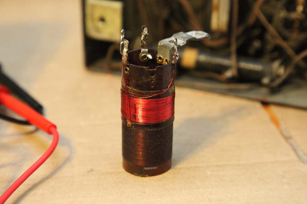
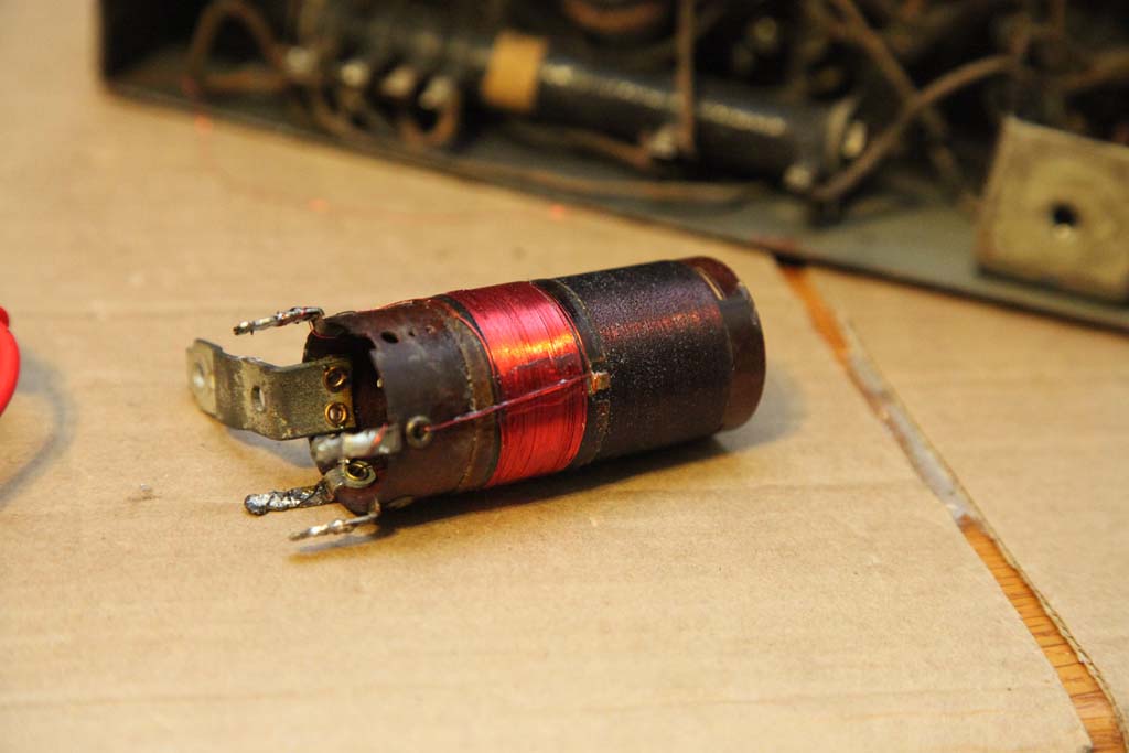
The 1st RF output transformer coil.
Did not photograph it before, so here's after. The new winding is obvious (the one closest to the bracket).


Just have soldered it in.
(This post was last modified: 01-31-2014, 10:10 PM by morzh.)
Users browsing this thread: 4 Guest(s)
|
|
Recent Posts
|
|
Shadow Meter Bulb
|
| Phorum members, I am trying to find the bulb # for PHILCO Shadow Meter part number 45-2180 that is from a 37-640 chassis...georgetownjohn — 06:53 PM |
|
Philco 41-608 changer coupler
|
| 3D-printing...short of machining, of course.
Or molding.morzh — 05:20 PM |
|
Philco 41-608 changer coupler
|
| Thanks, Morzh.
That solves the issue of the rubber pieces. Now, I need to find a way to replicate the pot metal piec...alangard — 05:07 PM |
|
12' Philco
|
| If it is 12', either Kareem or Andre would have to jump pretty high to look at the front panel.
Kareem would have an e...morzh — 01:48 PM |
|
12' Philco
|
| And here's a story about the tires on the truck. Same "no-stoop" guy must have installed these! Take care a...GarySP — 01:17 PM |
|
Hickok AC51 tube tester
|
| I think they have only shown the secondaries of the transformer.
Two of them feed the rectifiers' filaments.morzh — 12:58 PM |
|
IF can wire size and Rubber mounts?
|
| Arran
If the wire inside cans is the gauges you mentioned, the sole reason for that would be mechanical, to stiffen t...morzh — 12:56 PM |
|
12' Philco
|
| Rod,
Yes, I know, but the Giant Philco is not around anymore either, so I go by whoever was alive fairly recently.
H...morzh — 12:54 PM |
|
Hickok AC51 tube tester
|
| Absolutely no one is going to reverse engineer that circuit. Even the iron core is missing.RodB — 10:37 AM |
|
IF can wire size and Rubber mounts?
|
| Thanks to both members for your help regarding wire and tuner mtg supports. regards--Johngeorgetownjohn — 09:33 AM |
|
Who's Online
|
| There are currently no members online. |

|
 
|


![[-] [-]](https://philcoradio.com/phorum/images/bootbb/collapse.png)


