Welcome Guest! Be sure you know and follow the Phorum Rules before posting. Thank you and Enjoy! (January 12) x

Thread Closed
Thread Rating:
  • 0 Vote(s) - 0 Average
  • 1
  • 2
  • 3
  • 4
  • 5

cap questions on model 89 (version 6 schematic)
#1

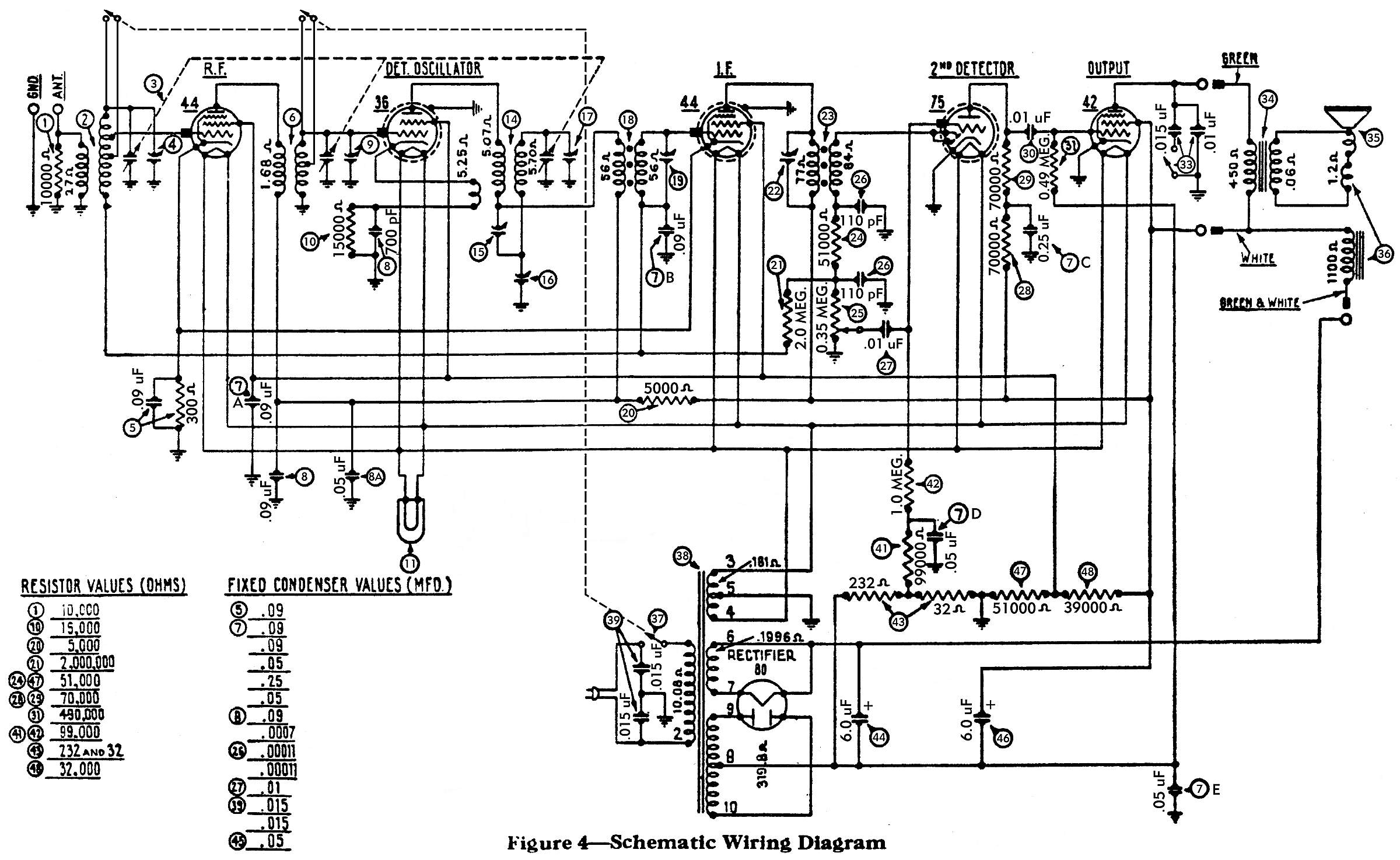
I really could use another pair of eyes and some good advice here from those more experienced than I. I'm trying to replace the caps in the #7 Filter condenser bank. There are 5 caps in that "bank", each are number 7 on the attached schematic. I'm trying to find where the .09 mfd's go? It almost looks like two of them go to the #44 RF tube on the front corner of the chassis. The other end goes to ground, of course.

The other question I have concerns the #5 bakelite block. There's a .09 mfd cap in the block along with a 300 ohm resistor. Should there be a wire going from one terminal of the block to the #41 (99,000 ohm) resistor? There are two wires coming from the variable capacitor going to the ground terminal on the bakelite block. Is that correct? Also does one wire from this block go to the antenna coil?

I'm sure to most of you, these will all appear to be obvious. I just want to verify that what I'm doing is correct. You can never be too sure! Icon_smile Thanks in advance.


Greg V.
West Bend, WI
Member WARCI.org
#2

It looks like 1 .09 goes to the grid of both 44's and the 36 the other .09 goes to coil #18 and the ant coil
#3

The #5 block is in series to ground from pin 4 of both 44's. They are probably just using the ground conection on the block because it was the closest/convenient ground.
#4

The cap going to resistor 41 should be a .05
#5

Thanks, tab. My chassis was a mess... someone, sometime long, long ago added and replaced a bunch of stuff and so much of what was reconnected was soldered onto the wrong lugs. I'm going through the schematic with a highlighter pen trying to trace out each and every wire / connection / component. A daunting process. The .05 cap between the 41 & 42 resistors was an easy one to find. But on my chassis, there was a wire going from the #5 block to the 41 resistor. I'm thinking it doesn't belong there.

Greg V.
West Bend, WI
Member WARCI.org


Users browsing this thread: 1 Guest(s)
[-]
Recent Posts
Philco 42-345 Restoration/Repair
The 2 towns you mentioned "Frustrated" and "Give Up" are places we have all been. Relax, take 5, thi...Paul Philco322 — 03:23 PM
Philco 89 Code 123 Osc Coil
Thanks for posting that information!klondike98 — 03:14 PM
Philco 42-345 Restoration/Repair
From what I see is the blue cap was added by someone after the radio was sold presumably to replace cap 40A. I can't tel...RodB — 03:12 PM
Philco 42-345 Restoration/Repair
Correction My original picture shows #40 cap, blue cap and #42 resistor connected.osanders0311 — 02:23 PM
Philco 42-345 Restoration/Repair
Well guys I am stuck, frustrated and about ready to give up. For starters all I'm getting from the speaker is a humming ...osanders0311 — 02:17 PM
[split] New member...
Thanks.  I'll try that.HowardWoodard — 01:13 PM
[split] New member...
You may have to start further back with your signal injection at the IF signal grid, then tune the second IF transformer...RodB — 10:28 AM
[split] New member...
Well, with the replacement tuning assembly, I have finally put the unit back together and aligned the dial.  The first s...HowardWoodard — 01:01 AM
Philco Model 16 wiring question
Well, finding a short is easy. Like I said, disconnect the transformer's secondary windings and see if it persists. If...morzh — 09:48 PM
Restoring Philco 96
Nice one!Stan the Man — 09:37 PM

[-]
Who's Online
There are currently 1018 online users. [Complete List]
» 3 Member(s) | 1015 Guest(s)
AvatarAvatarAvatar

>