Welcome Guest! Be sure you know and follow the Phorum Rules before posting. Thank you and Enjoy! (January 12) x

Thread Closed
Thread Rating:
  • 0 Vote(s) - 0 Average
  • 1
  • 2
  • 3
  • 4
  • 5

cap questions on model 89 (version 6 schematic)
#1

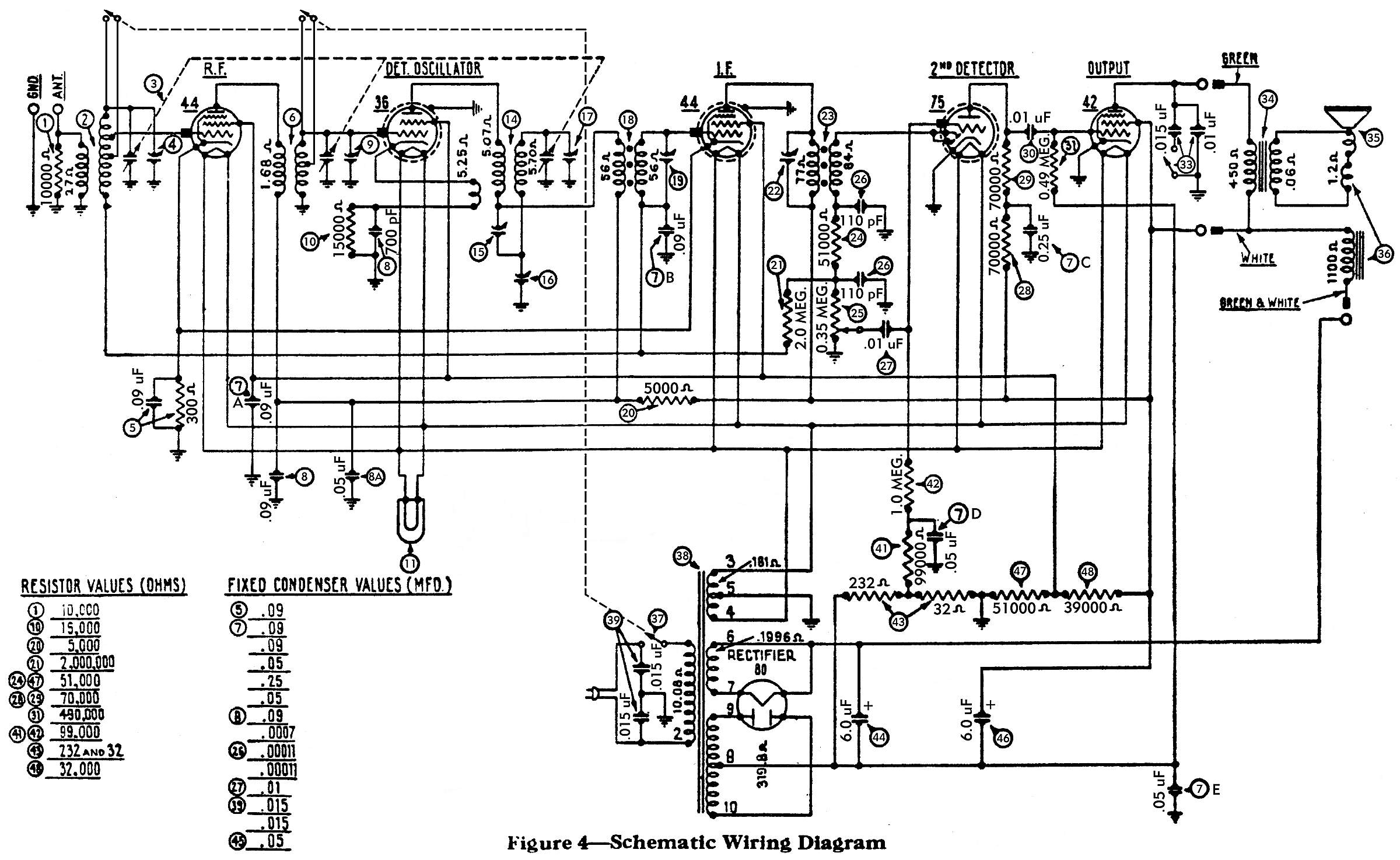
I really could use another pair of eyes and some good advice here from those more experienced than I. I'm trying to replace the caps in the #7 Filter condenser bank. There are 5 caps in that "bank", each are number 7 on the attached schematic. I'm trying to find where the .09 mfd's go? It almost looks like two of them go to the #44 RF tube on the front corner of the chassis. The other end goes to ground, of course.

The other question I have concerns the #5 bakelite block. There's a .09 mfd cap in the block along with a 300 ohm resistor. Should there be a wire going from one terminal of the block to the #41 (99,000 ohm) resistor? There are two wires coming from the variable capacitor going to the ground terminal on the bakelite block. Is that correct? Also does one wire from this block go to the antenna coil?

I'm sure to most of you, these will all appear to be obvious. I just want to verify that what I'm doing is correct. You can never be too sure! Icon_smile Thanks in advance.


Greg V.
West Bend, WI
Member WARCI.org
#2

It looks like 1 .09 goes to the grid of both 44's and the 36 the other .09 goes to coil #18 and the ant coil
#3

The #5 block is in series to ground from pin 4 of both 44's. They are probably just using the ground conection on the block because it was the closest/convenient ground.
#4

The cap going to resistor 41 should be a .05
#5

Thanks, tab. My chassis was a mess... someone, sometime long, long ago added and replaced a bunch of stuff and so much of what was reconnected was soldered onto the wrong lugs. I'm going through the schematic with a highlighter pen trying to trace out each and every wire / connection / component. A daunting process. The .05 cap between the 41 & 42 resistors was an easy one to find. But on my chassis, there was a wire going from the #5 block to the 41 resistor. I'm thinking it doesn't belong there.

Greg V.
West Bend, WI
Member WARCI.org


Users browsing this thread: 1 Guest(s)
[-]
Recent Posts
Philco model 40-100
You may be able to make the part out of wood. The particular vendor has a habit of disassembling radios and selling the...MrFixr55 — 10:09 PM
Philco 46-480 Electronic Restoration
Used to get to Bentonville when I worked for a Walmart vendor....nice and sleepy back then. PaulPaul Philco322 — 09:49 PM
Philco Model 249 made in England
Did Garrard produce stand-alone turntables? The reason I ask is, when I was a kid my grandfather gave me a KLH Model 20 ...jrblasde — 09:37 PM
Philco Model 249 made in England
Neat looking set, definitely Euro- style. I am guessing that this is solidstate due to the vent holes (or lack thereof,...MrFixr55 — 09:32 PM
Philco 46-480 Electronic Restoration
Haha, thank you sir! I’ve been eyeballing a 47-1230 console for sale over north of Bentonville, Arkansas for a while. Pr...jrblasde — 09:18 PM
Philco 46-480 Electronic Restoration
@ Joseph, get off the porch and run with the dogs. You fixed one, grab another. @ Morzh, I think that we are the same ...MrFixr55 — 08:59 PM
Philco Model 249 made in England
Wow! Now that is something! I’ve never seen a Philco like that, but it’s pretty mid-century.jrblasde — 06:40 PM
Philco 46-480 Electronic Restoration
I've run the radio for a couple of hours today, and all is well. It's a remarkable sounding radio! I'll go ahead and upl...jrblasde — 06:05 PM
Philco Model 249 made in England
Gary - Thanks for responding!  I hadn't actually taken possession of it at the time of my post but since you said it was...fklown — 03:32 PM
Philco model 40-100
Marion; Replacing volume controls was something some service shops did in years gone by to make a little extra profit...Arran — 03:24 PM

[-]
Who's Online
There are currently 481 online users. [Complete List]
» 3 Member(s) | 478 Guest(s)
AvatarAvatarAvatar

>