Philco model 610 rebuild - by Tim P.
Posts: 1,204
Threads: 84
Joined: Jan 2014
City: Annapolis, IL
State, Province, Country: USA
I have my 70 basically done, and am working out a few lingering bugs. I am starting the rebuild of a model 610. Is there anything specific about this model that I should be aware of or problems that I should look for besides the usual caps, tubes and resistors? Is this a model prone to coil failures? Any history or threads on this would be of great help.
I know nothing of the history of this set other than it is an abandoned house find, buried in dust, and even had termites in the cabinet! Thankfully they didnt do much damage. I am also glad they dont like to eat electronics! It has had some work done, like the elecrolytics replaced many years ago, a replaced volume control and some work around the #45 bakelite. Other than that, it looks mostly undisturbed.
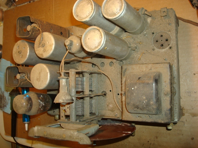
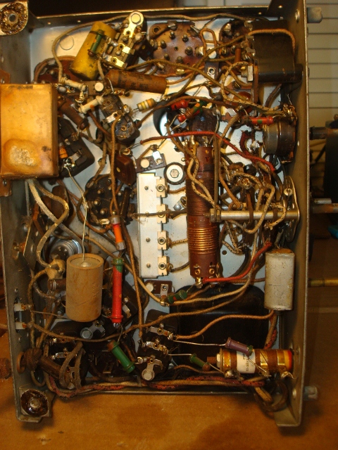
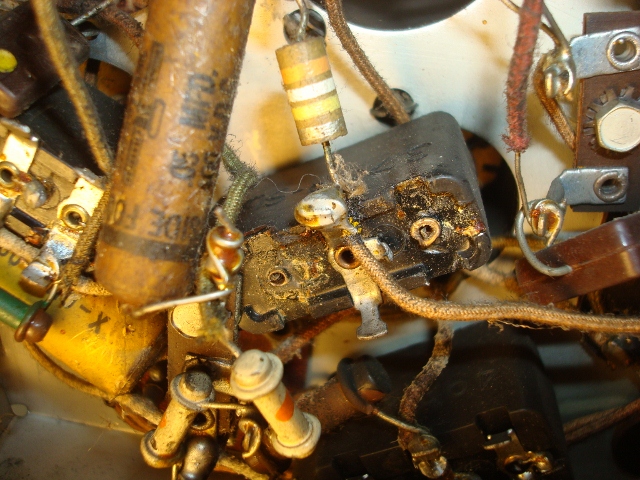
Here is the problem area. A shot of an undisturbed chassis would be of help. This is the #45 bakelite, which I think is a single .015 cap.
Thanks for your help and advice!
If I could find the place called "Somewhere", I could find "Anything" 
Tim
Jesus cried out and said, "Whoever believes in me , believes not in me but in him who sent me" John 12:44
Posts: 16,476
Threads: 573
Joined: Oct 2011
City: Jackson
State, Province, Country: NJ
Yes, the layer of dust indeed looks intimidating. 
Posts: 1,562
Threads: 56
Joined: Nov 2008
City: Sedona, AZ/Placentia/CA
Nice picture Tim. You need to lift that block and read the number off the side. I suspect if it is a single cap in there it goes from end to end, one end probably ground. The center hole appears to have had no internal connection as you see no wire coming up. It could have been used as just a connection point for various other wires. The end connections clearly show wires coming up through them. That .05 was probably a replacement cap when the original inside the block went bad.
Refer to the number on the side and Chuck's nice reference to determine what was in there and where attached.
Good luck, nice looking radio.
Jerry
A friend in need is a pest! Bill Slee ca 1970.
Posts: 1,204
Threads: 84
Joined: Jan 2014
City: Annapolis, IL
State, Province, Country: USA
Thanks Jerry. It does look like a single. The center terminal hasnt been soldered to through the rivot. The number on the side is 3793-SU. It looks to be a single .015.
I have pulled the electrolytics and have a little confusion about things. The #41 cap is shown in the schematic as a 16mf to chassis gnd. The layout diagram shows it as the cap that grounds through a couple of resistors (to the HV center tap) - 8mf stamped (30-2049-M) on the can. This is the left cap looking at the rear. I think the #41 and #54 may be reversed, but I am not sure. The numbers on the can are: 30-2118s, which is the cap in the middle, labelled #54, and 30-2025, which is the rear cap closest to the side (RH from rear). I dont see any referance to these numbers in Chucks site. Clarification appreciated. Any problem replacing the 8mf caps with 10mf 450v?
Another question is about the #32 bakelite. It looks like a .00011 dual. Is this a mica that doesnt need to be disturbed? It's number is 8035-DG. I'm inclined to leave it be unless I hear otherwise.
A few other notes: the # 23 bakelite has the center terminal clipped off, but I dont see anything else connected in its place. That is about as far as I have gotten.
If I could find the place called "Somewhere", I could find "Anything" 
Tim
Jesus cried out and said, "Whoever believes in me , believes not in me but in him who sent me" John 12:44
Posts: 1,562
Threads: 56
Joined: Nov 2008
City: Sedona, AZ/Placentia/CA
Tim, nice to post a schematic with your thread. Looking at your first picture from the top of the radio it appears the center rear can does not go to chassis ground. Note the cardboard liner between the can and mounting clamp. You should be able to read cap values off the cans directly. Ten mfd caps should work dandy for the 8s.
General consensus is that dual .00011 may or may not be mica! Don't take a chance and stuff it.
A friend in need is a pest! Bill Slee ca 1970.
Posts: 1,703
Threads: 55
Joined: Sep 2005
City: Evanston, IL
Those 110 pF caps are wax-paper-foil.
Use replacement 110pF silver-micas.
Posts: 1,204
Threads: 84
Joined: Jan 2014
City: Annapolis, IL
State, Province, Country: USA
Got ya on the micas. I found 100 and 120 pf caps. Would either of these be ok or should I parallel them with 10pf each? I was looking at the chassis wrong on the lytics, was looking at the diagram from below. Should have said it was closest to the power cord. Sorry for the mis-com. Anyway, I'll trace down things and go by the schematic. They could have put them in the wrong location on the diagram. I'm not sure how to post shots of schematics here - yet.
If I could find the place called "Somewhere", I could find "Anything" 
Tim
Jesus cried out and said, "Whoever believes in me , believes not in me but in him who sent me" John 12:44
(This post was last modified: 03-18-2014, 03:35 PM by TV MAN.)
Posts: 1,703
Threads: 55
Joined: Sep 2005
City: Evanston, IL
Those value should work ok, but 600V Dipped Silver-Mica caps are available at most parts distributors. Digi-Key, Mouser, etc.
Digi-Key p/n CD15FD111GO3F-ND
Mouser p/n 598-CD15FD111JO3F
Paralleling caps is not good idea. A "glob" of caps could make adjustments problematic, with extra lead lengths, etc.
Chuck
Posts: 178
Threads: 19
Joined: Feb 2014
City: The Motor City,Detroit MI
Tim, I believe I have the same discrepancy on my chassis. I'll try to get detail when I get home.
I didn't know about the .00011 caps. I planned on leaving them in. I already put my order in for caps. I'll have to add them to my next order.
Our two threads should be merged.
(This post was last modified: 03-19-2014, 12:39 PM by Kestas.)
Posts: 1,204
Threads: 84
Joined: Jan 2014
City: Annapolis, IL
State, Province, Country: USA
I started the electrolytic cap rebuild and found three different types, a tar filled dry cap, a dry wet cap, and a wet-wet cap. I am amazed that after 80 years this wet cap was still wet! I went through some threads and articles on these, and here are a few shots of what I did.
The tar pit:
I knew this one was different. This is the 1st cap off the rectifier tube (#56). I used a tubing cutter in this one, then since the stuff inside was rather fond of it's present location, I had to use a heat gun, lag screw and vice. Finally got it to seperate, then had lots of fun digging the rest of the tar out. Be careful not to dent or crush the can. Also on this one, seemed the lettering wanted to rub off.
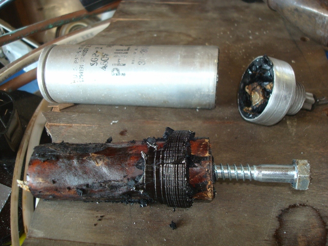
I used the 1" pvc, cut a line through so it would squeeze and go into the can.
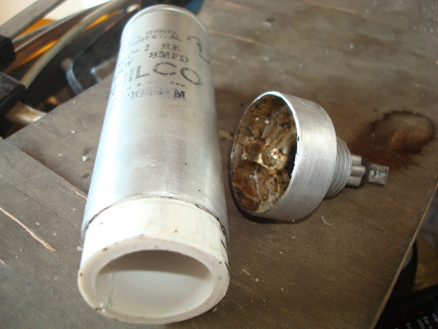
Here is the finished product ready to install. I used hot glue to secure the new capacitor in place, and ran the wires out the bottom. My next post will show in better detail this step.
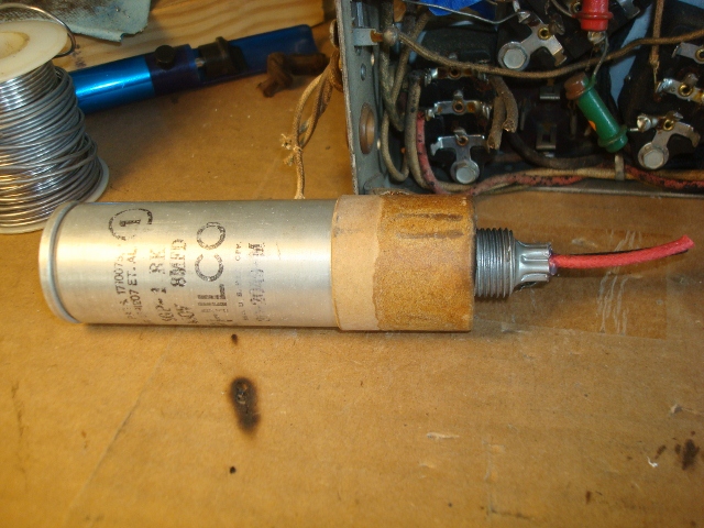
If I could find the place called "Somewhere", I could find "Anything" 
Tim
Jesus cried out and said, "Whoever believes in me , believes not in me but in him who sent me" John 12:44
Posts: 1,204
Threads: 84
Joined: Jan 2014
City: Annapolis, IL
State, Province, Country: USA
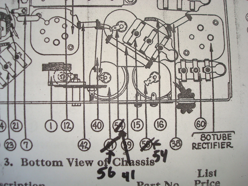
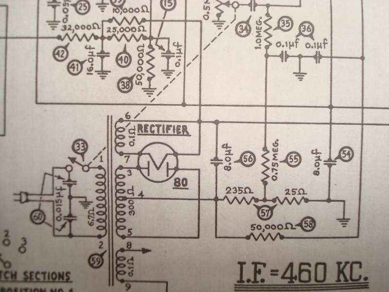
I have traced down the diagram and found the under chassis location number of the caps in the diagram is wrong. The schematic is correct. Looking at the chassis from the top rear (dial to the front), the right rear cap is the input cap off the rectifier tube #56 8mf, and is the insulated ground, the cap to the left of that, nearest the 80, is the output cap, #54 8mf, the cap in the middle closest to the power transformer, with all the resistors under it is the #41, 16mf cap. I used a 10mf 450v cap for the 8's.
Here are some shots of the wet can rebuild:
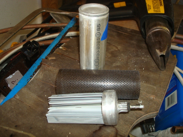
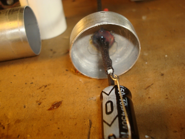
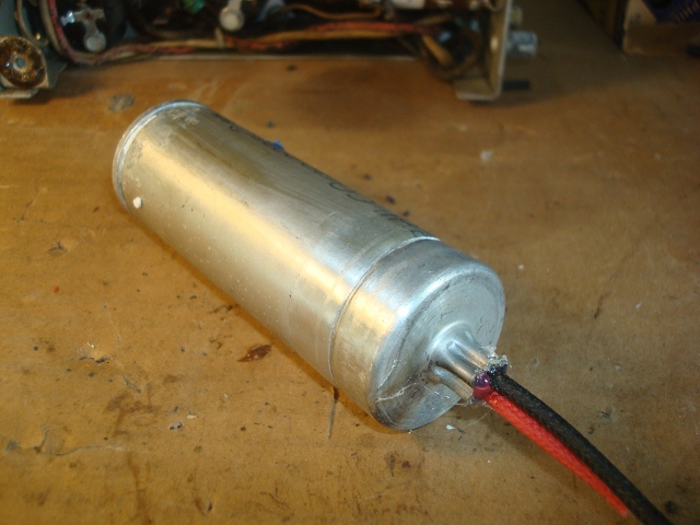
I used a tubing cutter on this one, but it was a little tricky. It kept wanting to track off. The next one, didnt go good at all with the tubing cutter, so I quit and used a hack saw to finish. Not real proud of it, but it will be hidden in the clamp. I found it useful to mark the cans with a marker to help the line up when done. I didnt pot the caps, but did seal them through the hole where I ran the wires go through with hot glue. Holds things in place real nice. I used shrink wrap over the + wire of the cap. I didnt glue the can together and left enough wire inside to make re-replacement easier for the next time around. The clamp seems to hold things in place. Ill post a shot when I have them in place and tested.
If I could find the place called "Somewhere", I could find "Anything" 
Tim
Jesus cried out and said, "Whoever believes in me , believes not in me but in him who sent me" John 12:44
(This post was last modified: 03-21-2014, 10:15 AM by TV MAN.)
Posts: 1,204
Threads: 84
Joined: Jan 2014
City: Annapolis, IL
State, Province, Country: USA
Here a couple pics of the schematic and diagram. I marked the caps in question with (what I believe) are the correct positions. Hope this helps clarify.
If I could find the place called "Somewhere", I could find "Anything" 
Tim
Jesus cried out and said, "Whoever believes in me , believes not in me but in him who sent me" John 12:44
Posts: 34
Threads: 7
Joined: Jan 2012
City: Woodstock Illinois
Good luck with your rebuild - I know those schematic errors threw me off the scent a bit !
(This post was last modified: 03-21-2014, 02:18 PM by Chris Cusick.)
Posts: 1,562
Threads: 56
Joined: Nov 2008
City: Sedona, AZ/Placentia/CA
Nice job Tim.
Jerry
A friend in need is a pest! Bill Slee ca 1970.
Posts: 1,204
Threads: 84
Joined: Jan 2014
City: Annapolis, IL
State, Province, Country: USA
I have some of the bakelite blocks rebuilt and two of the filter caps in. I used Morzh's technique on the bakelites. I had two of them that fought me tho. I think the wax must be a little softer on some over others, and my allen wrench tended to push through instead of pushing the stuff out. I could still dig out with a small screwdriver, just wasnt as neat as I'd like. They were identical caps, so I hope the rest will push out like the line filter. I found the reason for the clipped lead on the #45 block - looks like R30 has been pretty warm at some point, probably from a leaky cap in the block, so they "fixed" it by clipping the lead. Another note is the wires from the plate of the 42. The tone control wire was bad bad bad. Also the wires from the speaker were bad, so they got replaced. I replaced the wire all the way to the 42 plate since it would crack the insulation if flexed - with full B+ on this one, I wanted a good wire.
I found several resistors that were off spec as well, R39, 38, 16, 55, 18 and 30. I am waiting on a few parts to come, hopefully by the weekend, can power up and see 'whats in the box'.
If I could find the place called "Somewhere", I could find "Anything" 
Tim
Jesus cried out and said, "Whoever believes in me , believes not in me but in him who sent me" John 12:44
Users browsing this thread:
|
|
Recent Posts
|
|
Need to purchase some accessories for restoration of my Old Philco Radio
|
| Hi Paulo,
Welcome to the Philco Phorum.
I can see why you want to find good reproduction parts. That is a bea...MrFixr55 — 11:10 PM |
|
HiFi (Chifi) tube amp build - but my own design.
|
| Tim,
I have some bakelite sockets in my work shop that I can dig up. I believe quite a few are NOS. I will take photo...RodB — 10:03 PM |
|
Philco 610B oscillator wiring
|
| > The cathode as noted is wired directly to the ground side of the heater filament for that tube, not to the #17 and ...Radioroslyn — 08:12 PM |
|
HiFi (Chifi) tube amp build - but my own design.
|
| Tim;
I noticed your post a little late, but I would take one of the junk sockets and try to break a chunk out of it wi...Arran — 08:07 PM |
|
Need to purchase some accessories for restoration of my Old Philco Radio
|
| Here is a list of resources found in our online library that you might find useful. Mike's Gobs of Knobs email addres...klondike98 — 01:46 PM |
|
First Radio restoration
|
| Hi Tubeman,
Welcome to the Philco Phorum. Phamily Phriendly Pfun with Phine Pholks Phull of Philco Phacts. (See a p...MrFixr55 — 12:33 PM |
|
First Radio restoration
|
| You could post in the WANTED ADs section here on the Phorum and see if anyone has an RF generator that they want to sell...klondike98 — 11:55 AM |
|
Zenith H725
|
| Good ideas, thank you Arrange and Rich. I have the adhesive aluminum foil already and can try that immediately.
More ...EdHolland — 10:18 AM |
|
Graphics for majestic 1050 dial glass.
|
| Murf;
I found this thread on the ARF, the first photo has a pretty good view of the dial glass.
Regards
ArranArran — 01:12 AM |
|
Zenith H725
|
| hello Ed,
how about that speacial tape used for ducting it's like foil or how about thin piece of
aluminum roof flash...radiorich — 12:19 AM |
|
Who's Online
|
| There are currently no members online. |

|
 
|


![[-] [-]](https://philcoradio.com/phorum/images/bootbb/collapse.png)


