Posts: 451
Threads: 85
Joined: Nov 2011
City: Cumming, GA
I have a RCA-68R3 Riders vol. 16 pages 39-43.
http://www.nostalgiaair.org/PagesByModel...015092.pdf
I have recapped and tested all the tubes, checked the resistors and replaced those over 20%. The AM plays fine the FM does not!
I have checked all the voltages which are on the prints and they are within 10-20%
I have checked all the coils for an open and they are as follows. Did not subtract for the leads and I was able to isolate at least one end.
T1 a&f .3 c&d .4
T2 a&f 10 c&d 11
T3 a&f .8 c&d 1.5
T4 a&f 11.8 c&d 8.8
T5 a&b .9 c&d .9
T6 d&e .6 d&f 1.1 e&f 1.1
While poking around with the voltmeter on V5 6ALS ratio detector pin7 & T6 e I get a couple of faint stations with the volt meter connected.
Now this radio does not have mica caps but small wax covered tubular caps should I go ahead and change them?
Looking for ideas on where to check next.
Thanks, Eric
Posts: 893
Threads: 9
Joined: Mar 2008
City: Vieques, PR USA
State, Province, Country: PR
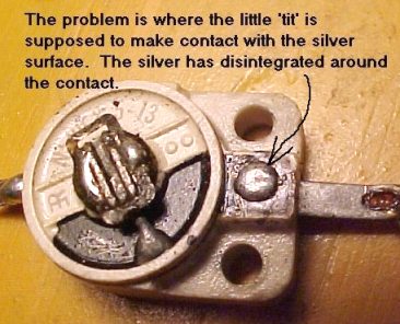
Maybe a clue. On mine I was able to hear some weak stuff down at the bottom of the band. Messing with the RF trimmer and coil made them louder but the osc trimmer wouldn't move them up the band significantly.
Turns out the osc trimmer was bad. Once replaced and everything realigned it worked ok. I'd suspect the trimmer as being the prime suspect. Many people have reported the exact same problem.
And yes, you should replace all wax paper caps.


(This post was last modified: 07-16-2014, 07:32 PM by exray.)
Posts: 451
Threads: 85
Joined: Nov 2011
City: Cumming, GA
Well I know what I will be doing tomorrow! Great pictures and I do get a few very faint stations on the low end of the scale.
Thanks
Posts: 451
Threads: 85
Joined: Nov 2011
City: Cumming, GA
Ok, As the song says " I Can See Clearly Now" This is exactly my problems
I'm going to start at the bottom.
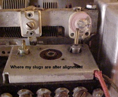
3 My slugs look about like yours about 5/16 on the right and 5/8 on the left.
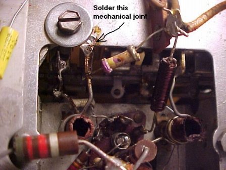
2 I have no screw there I will put one there and solder the two parts of the chassis
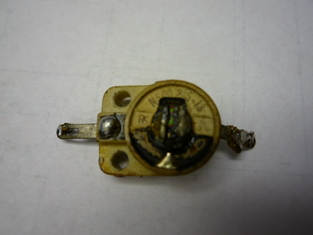
1 The silver on the inside center part is pretty much eaten up the lower where you indicate is black. Can I resolder the part you indicate? Is it part c-33 2.5-13 mmf? Can I buy a replacement or put in a fixed?
Posts: 893
Threads: 9
Joined: Mar 2008
City: Vieques, PR USA
State, Province, Country: PR
I think you'll find that it won't take solder. Maybe silver solder would work?
You can't use a fixed cap there. You'll probably have to use a different type of trimmer and figure out a method of mounting. AES used to have some surplus ones that were an exact fit but that was a decade ago.
Posts: 16,493
Threads: 573
Joined: Oct 2011
City: Jackson
State, Province, Country: NJ
Silver solder with tin-lead just fine but if oxidized badly it won't take the solder.
You can also buy a trimmer cap and solder it in place.
Or use a patch of copper foil and such, conductive paint possibly.
If trying to solder be careful not to take the remnants of the silver off, or this will be it for this trimmer.
Posts: 893
Threads: 9
Joined: Mar 2008
City: Vieques, PR USA
State, Province, Country: PR
I have restored two Tandberg (Norwegian) radios from abt 1940 that used similar caps throughout the multiband RF and osc stages. Nearly every one was bad in a similar manner. Aargh!
Search on ebay and you'll probably be able to find something usable. Even those little modern plastic trimmers can be made to work here since there isn't any significant voltage to contend with.
Posts: 451
Threads: 85
Joined: Nov 2011
City: Cumming, GA
It will have to wait till Monday as I'm headed to Lexington Ky till Sunday. I do have some questions,
If it is c-33 on the print 2.2-13mmf I have a 5 &10mmf I would like to solder one of them in to see if I can get the FM to work do I need to remove the trimmer or can I parallel it?
Posts: 893
Threads: 9
Joined: Mar 2008
City: Vieques, PR USA
State, Province, Country: PR
Well...the existing cap is essentially open but it presents a pf or two of stray capacitance because its still there. Nothing wrong with trying to patch in your 10pf trimmer across it. May not be the best solution but worth a try.
Posts: 451
Threads: 85
Joined: Nov 2011
City: Cumming, GA

I have removed the trimmer C33 2.5-13pf and put in a 10pf silver mica while unsoldering C1 (27pf) came apart (could have been part of the original problem) so I had a 24pf I put it in. When I adjusted L3 and L1 and especially C31 it came alive. Now while doing a google search for 2.5-13pf trimmer I got a hit that took me to one of the electronic sellers and there it was the same part mounting holes and all so I ordered a couple of them should be here around the end of the week. I will change it as the far end around 108fm is a little faint.
(This post was last modified: 07-21-2014, 05:30 PM by Eric.)
Posts: 893
Threads: 9
Joined: Mar 2008
City: Vieques, PR USA
State, Province, Country: PR
Good luck!
That cap is only for setting the tuning range for the local oscillator to get reception showing at the right places on he dial. The combination of it and the associated coil will establish the correct 88-108 tuning range. So if you figure a mid-setting of say 8pf then any trimmer of 2-10, 3-15, 5-20, etc can work.
Once that's established, the other coil/cap combo will establish peak reception performance for the two ends of the band.
Unfortunately, IMHO, the 68R* series aren't going to set the sky ablaze with superior FM reception. The poor dog doesn't have an RF Amp on the FM band.
(This post was last modified: 07-21-2014, 08:22 PM by exray.)
Posts: 451
Threads: 85
Joined: Nov 2011
City: Cumming, GA
exray
It actually works pretty good I did play with the slugs to get the proper dial settings.
Thanks for the help
Users browsing this thread: 1 Guest(s)
|
|
Recent Posts
|
|
The list of my radio & TV collection!
|
| Yes, Michael. But strangely enough, I managed to keep the original veneer. I must admit that I don't really like it, so ...RadioSvit — 02:21 PM |
|
The list of my radio & TV collection!
|
| Good radio.
I bet there was a lot of veneer fixing.morzh — 02:16 PM |
|
Philco 46-480 Electronic Restoration
|
| >> it is because I am retired and a little demented.
You have just the right amount of it. No perfectly sane p...morzh — 02:14 PM |
|
The list of my radio & TV collection!
|
| Old Zenith 5S-29 tube radio. First turn-on after repair and reception quality testing. Demonstration of the operation of...RadioSvit — 01:27 PM |
|
Philco 42-345 Restoration/Repair
|
| Welcome to the Phorum, osanders0311! Regardless how far you intend to restore this set, first priority should be replac...GarySP — 11:51 AM |
|
Philco 46-480 Electronic Restoration
|
| Joseph, it is because I am retired and a little demented. My problem is that I wanted to own a collection that spans th...MrFixr55 — 11:29 AM |
|
Philco 46-480 Electronic Restoration
|
| Wow, here I am with only two restored radios. I’ve got to boost those numbers! If you can’t run with the big dogs, you m...jrblasde — 10:04 AM |
|
Philco 46-480 Electronic Restoration
|
| Hello MrFixr55,
That will for sure keep you out of trouble!
Last Sunday was spent mostly doing yard work anyway the we...radiorich — 09:50 AM |
|
Philco 46-480 Electronic Restoration
|
| Throw in all the Audio equipment that has to be kept in a bedroom (my office)L. 8 portable self contained PA speakers, ...MrFixr55 — 07:40 AM |
|
Philco 42-345 Restoration/Repair
|
| Looking at the pic supplied by Rod B, you can duplicate the missing loop antenna. 10 gauge copper wire can be used to m...MrFixr55 — 01:20 AM |
|
Who's Online
|
There are currently 366 online users. [Complete List]
» 1 Member(s) | 365 Guest(s)
|
|
|

|
 
|


![[-] [-]](https://philcoradio.com/phorum/images/bootbb/collapse.png)


