Posts: 16,476
Threads: 573
Joined: Oct 2011
City: Jackson
State, Province, Country: NJ
Might as well be 666.
1. Pre-existing recap (bad).
2. A daughterboard coveing a tuning cap mount screw which is also soldered and did not wantbto come out.
3. The output xfmr shot.
4. the filter choke shot.
5. missing tube shields (bought them) and a tube.
just occured to me, checked power input. At least there is continuity.
Wonder what else is there. I hope coils are OK, not looking forward to rewinding job(s).
Posts: 4,862
Threads: 54
Joined: Sep 2008
City: Sandwick, BC, CA
The filter choke, as in speaker field coil, is shot? As far as I know a model 66 has the same power supply design as a model 60 as in the speaker filed coil is used as the filter choke. I have no explanation for the output transformer being bad, those seldom go bad even if the power supply does.
Regards
Arran
Posts: 16,476
Threads: 573
Joined: Oct 2011
City: Jackson
State, Province, Country: NJ
Arran
The filter is a dual one.
The B+ is filtered by field coil.
But the power and biases filter for the oscillator and IF is filtered separately by the choke.
Possibly they wanted better decoupling for heterodyne.
Posts: 16,476
Threads: 573
Joined: Oct 2011
City: Jackson
State, Province, Country: NJ
While looking for substiute choke I looked at the specs: the max DC current is 10mA, at 70H inductnce and 2300 Ohm resistance.
While this seems like a lot of current for to SGs to pull, according to the voltage chart the SG votages are 80V while the rectifier voltage is probably 260-270V which makes the current about 8.7mA, close to the max of 10mA.
Hammond makes 20H choke for 20mA at 1.7k resistance. 20H is not 70H but it will bring the cutoff frequency from 7Hz to 12.5Hz, which is acceptable. The resistance could be brought up by serializing with a smll 600 Ohm resistor to keep the voltages though I think itbis not very important.
The output transformer will probably be 125-ACE or equivalent if I find a cheaper alternative, needs to have 87:1 ratio.
Posts: 4,862
Threads: 54
Joined: Sep 2008
City: Sandwick, BC, CA
Well that's a new one on me. I wonder why Philco would bother with an extra filter choke in a five tuber like this? The set is more or less a model 60 chassis with different band coverage, so why waste money adding an extra inductor that none of their competitors would have? I wonder if the power supply could be rewired to copy the model 60? It looks like capacitor #49 (5 uf) probably shorted out and damaged that silly choke. Possibly one of the capacitors in the tone control did the same and destroyed the output transformer primary, since it's a single ended #42 finding a replacement should not be a problem, you may even be able to find a salvaged Philco output transformer?
Regards
Arran
Posts: 16,476
Threads: 573
Joined: Oct 2011
City: Jackson
State, Province, Country: NJ
Already found the original xfmr in Oldradioparts.
Need a choke. Would by from Raiodaze but Oldradiophfarts needs $20 purchase.
Posts: 16,476
Threads: 573
Joined: Oct 2011
City: Jackson
State, Province, Country: NJ
A discrepacybin the sch: The 78 tube's suppressor is supposed to be connected to K.
Instead it goes directly to GND and it looks like a factory soldering even though the radio was "tended" to by some very sloppy person to say the least.
http://www.nostalgiaair.org/PagesByModel...013827.pdf
In the changes in Rider's sch thereis no such change.
Posts: 16,476
Threads: 573
Joined: Oct 2011
City: Jackson
State, Province, Country: NJ
Well, done with the recap. Except lytics.
Had some old Philco caps, restuffed them instead of those dipped caps someone installed.
Speaking of which: I am not sure what the deal is, I thought those were film capsnand not paper, they look moder enough....0.05uF cap was 0.1uF, 0.01uF is 0.015uF...both are 10% tolerance.
Well, many wires are broken so will have to re-establish those, and lytics are essential part as they also act as wire holders.
Posts: 16,476
Threads: 573
Joined: Oct 2011
City: Jackson
State, Province, Country: NJ
A-ha! Looked at the Changes, this was the last change from 12-1-34 about SG to GND. Zit is suppsed to allow uing 78E European type tube interchangeably with 78.
Posts: 264
Threads: 51
Joined: Aug 2014
City: San Antonio, TX
Also, the filter circuit has a famous mistake in the schematic. This shows the correction on C50. http://www.capeoldradio.com/cor_picts/Ph...467-S2.gif
Posts: 16,476
Threads: 573
Joined: Oct 2011
City: Jackson
State, Province, Country: NJ
Yes it is a famous mistake, it was first discussed here when found on a 90.
Indeed how does power a tube's plate connecting it to the GND via a cap  . The absnse of B+ filtering notwithstanding. They have it across multiple radios. One tie dot. Many confused people going nuts troubleshooting.
Though this only occured when rewiring, otherwise the wiring would be in place.
Posts: 264
Threads: 51
Joined: Aug 2014
City: San Antonio, TX
I have a question about reading the schematic for this model if I may highjack this thread for a second (if not, I quite understand). But I was looking at the part of the schematic for a 66 restoration that has caused me much heartache, and I noticed the section around the 6A7 had me scratching my head. The connections involving parts 8, 9, 10, 13, and 16 especially. I'm still struggling a bit with translating the schematic to the real wiring in the chassis, and in this case, the parts map below the schematic seems to contradict the schematic somewhat. Part 10 (50K resistor) seems to lie between the oscillator coil and the cathode of the 6A7, but the parts map seems to show the resistor grounding the coil to the chassis. Shouldn't part 10 connect to pin 6 of the 6A7 where parts 8 & 9 (flex ohm resistor and .05 uf cap) connect to one side of C13 along with the mica cap C12?
Posts: 16,476
Threads: 573
Joined: Oct 2011
City: Jackson
State, Province, Country: NJ
Either way can work.
The DC potential of the 1st grid should be that pf the Cathode, so it can be coil to GND via cap and the grid biased by the resistor to Cathode, or coil via resistor to Cathode.
http://www.radiomuseum.org/tubes/tube_6a7.html
Posts: 264
Threads: 51
Joined: Aug 2014
City: San Antonio, TX
Posts: 16,476
Threads: 573
Joined: Oct 2011
City: Jackson
State, Province, Country: NJ
Electrolytics
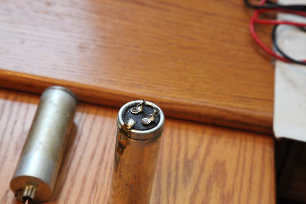
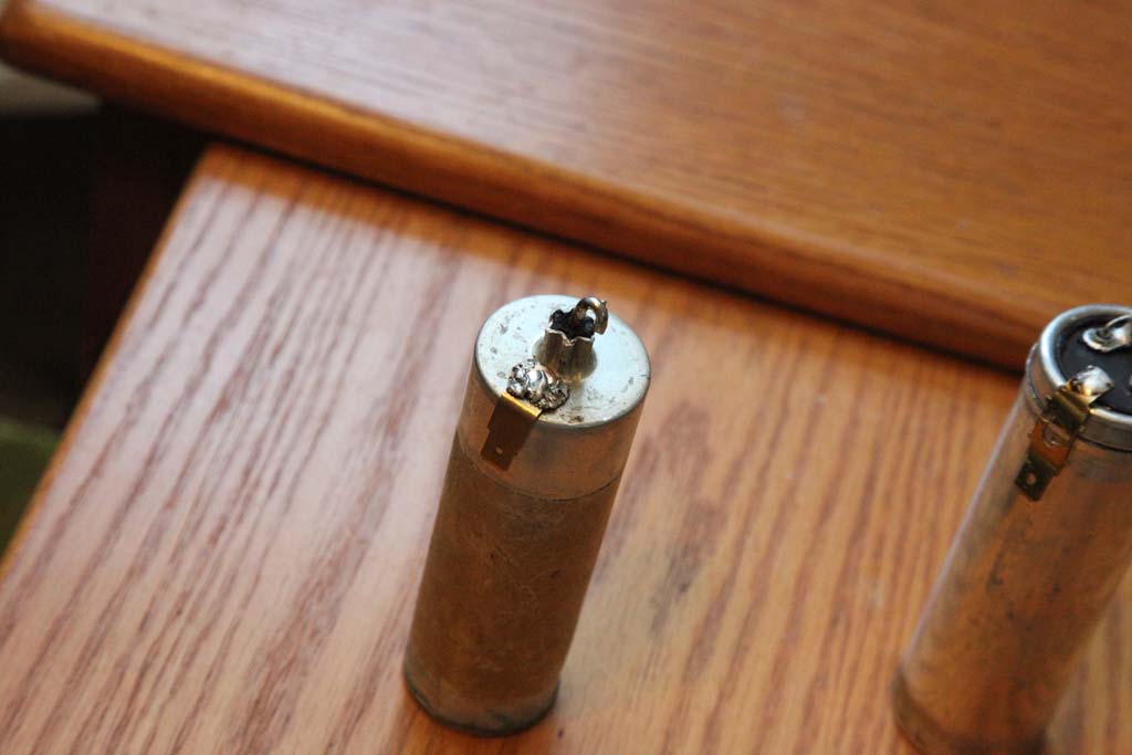
This is the way I did mine this time around:
On the dual I drilled out the lugs, riveted them with copper rivets, extracted the mandrel and threaded the caps through them, flooding with solder afterwards.
The negative I soldered to a brass QC, and it will go under the cardboard tube insulator to provide the connection.

On the single I used the copper-plated mandrel from that rivet as the pole (it is very rigid and solders well), and the minus is the same way - brass QC riveted to the body and soldered to the cap's lead, then it will go under the clamp that holds the caps to provide the connection (this one is connected to the chassis)

If you as why I did not simply use wires as I did most of the times, the answer is - I want these to provide the suppoprt for existing wiring the same way the originals did, so I do not have to splice and tape/heatshrink the connections. Makes it simple and the existing wires can be reused the same way they were before.
Users browsing this thread: 1 Guest(s)
|
|
Recent Posts
|
|
Need to purchase some accessories for restoration of my Old Philco Radio
|
| Hi Paulo,
Welcome to the Philco Phorum.
I can see why you want to find good reproduction parts. That is a bea...MrFixr55 — 11:10 PM |
|
HiFi (Chifi) tube amp build - but my own design.
|
| Tim,
I have some bakelite sockets in my work shop that I can dig up. I believe quite a few are NOS. I will take photo...RodB — 10:03 PM |
|
Philco 610B oscillator wiring
|
| > The cathode as noted is wired directly to the ground side of the heater filament for that tube, not to the #17 and ...Radioroslyn — 08:12 PM |
|
HiFi (Chifi) tube amp build - but my own design.
|
| Tim;
I noticed your post a little late, but I would take one of the junk sockets and try to break a chunk out of it wi...Arran — 08:07 PM |
|
Need to purchase some accessories for restoration of my Old Philco Radio
|
| Here is a list of resources found in our online library that you might find useful. Mike's Gobs of Knobs email addres...klondike98 — 01:46 PM |
|
First Radio restoration
|
| Hi Tubeman,
Welcome to the Philco Phorum. Phamily Phriendly Pfun with Phine Pholks Phull of Philco Phacts. (See a p...MrFixr55 — 12:33 PM |
|
First Radio restoration
|
| You could post in the WANTED ADs section here on the Phorum and see if anyone has an RF generator that they want to sell...klondike98 — 11:55 AM |
|
Zenith H725
|
| Good ideas, thank you Arrange and Rich. I have the adhesive aluminum foil already and can try that immediately.
More ...EdHolland — 10:18 AM |
|
Graphics for majestic 1050 dial glass.
|
| Murf;
I found this thread on the ARF, the first photo has a pretty good view of the dial glass.
Regards
ArranArran — 01:12 AM |
|
Zenith H725
|
| hello Ed,
how about that speacial tape used for ducting it's like foil or how about thin piece of
aluminum roof flash...radiorich — 12:19 AM |
|
Who's Online
|
| There are currently no members online. |

|
 
|


![[-] [-]](https://philcoradio.com/phorum/images/bootbb/collapse.png)


