Posts: 285
Threads: 27
Joined: Nov 2012
City: Tehachapi. California


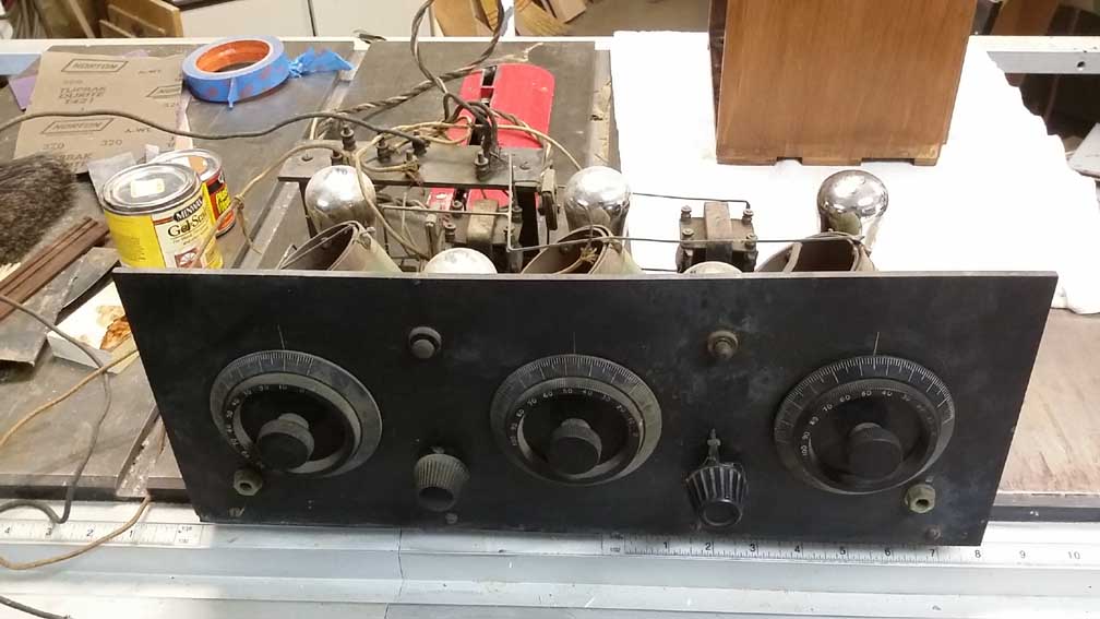
Can anyone identify this little beast? I am not sure it's worth messing around with.
!!!!!!!!!!!!!!!!!!!RESISTANCE IS FUTILE!!!!!!!!!!!!!!!!!!!!!!
/\/\/\/\/\/\/\/\/\
[Image:
http://philcoradio.com/phorum/images/smi...on_eek.gif] Chris
Posts: 285
Threads: 27
Joined: Nov 2012
City: Tehachapi. California
Part of my test is missing. The message is Can anyone identify this little beast? I am not sure it's worth messing around with.
!!!!!!!!!!!!!!!!!!!RESISTANCE IS FUTILE!!!!!!!!!!!!!!!!!!!!!!
/\/\/\/\/\/\/\/\/\
[Image:
http://philcoradio.com/phorum/images/smi...on_eek.gif] Chris
Posts: 7,300
Threads: 268
Joined: Dec 2009
City: Roslyn Pa
Don't know but it doesn't matter much there all about same. Check the audio xformers and rf coils. Looks like it may be a homemade job.
Terry
Posts: 285
Threads: 27
Joined: Nov 2012
City: Tehachapi. California
I have looked online and can't find one that looks like it. The murdock is close. I do know that they used batteries to power up. but I don't have a clue what voltages to use or how to hook it up. I was hoping to find a schematic for this one and maybe build a power supply. Right now its a long way from there.
Chris
!!!!!!!!!!!!!!!!!!!RESISTANCE IS FUTILE!!!!!!!!!!!!!!!!!!!!!!
/\/\/\/\/\/\/\/\/\
[Image:
http://philcoradio.com/phorum/images/smi...on_eek.gif] Chris
Posts: 3,152
Threads: 56
Joined: Apr 2011
City: Lexington, KY
Looks like a typical 5 tube TRF, possibly a home brew as Terry mentioned. Check the audios and RF like suggested. It probably uses 01A tubes, so at least check the filaments for continuity if you don't have a tube tester.
These are pretty simple sets and most are pretty standard, but watch this video to get a better understanding of these sets:
http://www.youtube.com/watch?v=oHMbrXRi3Uw
I will say the most rewarding experience I've had as a collector was years ago when I restored an old set like this and picked up some stations through the little horn speaker I had hooked up.
You might have to sketch out a schematic by following the wiring and components. If you look through Riders vol 1 you'll find a lot of similar schematics. That set looks a bit beat so it might not be the best three dial five tube battery set to cut your teeth on.
John KK4ZLF
Lexington, KY
"illegitimis non carborundum"
Posts: 4,870
Threads: 54
Joined: Sep 2008
City: Sandwick, BC, CA
Yes, that looks like a home brew, but a nicely made example though. The first point of failure is usually the interstage transformers, followed by the solder joints on the tube pins, and every other solder joint. Also the filament rheostats sometimes fail, although you can usually spot that as there will be physical breaks in it, and sometimes the RF coils will have an open winding or become unwound. Overall whoever made this chose good quality parts, I don't see any cheap pot metal bits like some of the factory built sets would have, and they were very fussy about how they laid out the wiring, buss bars with nicely bent joints. Electrically these are very simple but the construction was often very nice to look at.
Regards
Arran
Posts: 285
Threads: 27
Joined: Nov 2012
City: Tehachapi. California
I been messing around with this thing some today. I drew out a rough schematic. Also I found that two of the three main tuning caps were distorted at the bakelite pieces from age and stress. I worked on one so far and it now appears to work no more dragging. I still need to do the other one and every thing need cleaning and reconnecting. Its not been stored well most everything is lightly corroded. And yes the more I look at it the more it looks like a kit. No brand name so far. Must have been some rich kid's toy.
If this thing looks like it will work I will try using a small output transformer and speaker for the missing horn speaker. What do you think, maybe it has a 1/2 watt output? Its still a long way from that now.
I will work on it more soon with pics.
Chris
!!!!!!!!!!!!!!!!!!!RESISTANCE IS FUTILE!!!!!!!!!!!!!!!!!!!!!!
/\/\/\/\/\/\/\/\/\
[Image:
http://philcoradio.com/phorum/images/smi...on_eek.gif] Chris
Posts: 411
Threads: 42
Joined: Sep 2008
City: Ironton Ohio
If the trans is bad, you can bypass with caps and resistors. Look for 511 trans bypass in tech section is where I think I read it. Those trans are high impedance so they can be hard to check with a digital meter. the jack before the second trans is for headphones the one after is for the horn. Batteries should be 5va, (filament) 22, 45, 90vb (first trans, second trans, horn)on the ones I have anyway. Stewart Warner model 300 is a good generic trf schematic.
Posts: 7,300
Threads: 268
Joined: Dec 2009
City: Roslyn Pa
A 1/2 watt is going to be pretty close depending what tube you use for the output. 112A or 71A are the tipical ones. Any small sized output xformer will work fine. For the most part the load here is going to be about 3k for the 71A and 10K for the 112A. Am using a 112A in my two tube Crosley 51. Sound great with -9v bias.
GL
Terry
Posts: 285
Threads: 27
Joined: Nov 2012
City: Tehachapi. California
OK After being busy with a 56 tbird and some migraines. I finally got back to checking out the transformers and yes one of them is hopeless and the other has a broken wire that could be fixed. So after this and the fact it has other problems and since it's no cherry, I have lost interest. I think I will post it on the for sale section. Free just pay for shipping. Maybe somebody needs it for parts.
Thanks for the help.
Chris
!!!!!!!!!!!!!!!!!!!RESISTANCE IS FUTILE!!!!!!!!!!!!!!!!!!!!!!
/\/\/\/\/\/\/\/\/\
[Image:
http://philcoradio.com/phorum/images/smi...on_eek.gif] Chris


![[-] [-]](https://philcoradio.com/phorum/images/bootbb/collapse.png)


