Posts: 29
Threads: 7
Joined: Aug 2014
City: España
Posts: 7,300
Threads: 268
Joined: Dec 2009
City: Roslyn Pa
You are probably ok. It's used the ground the rotor . Just make sure that the other one is good and clean. Use a bit of DE Oxit to clean it up.
Terry
Posts: 29
Threads: 7
Joined: Aug 2014
City: España
Thank you very much.
I'll finish cleaning and I will use it well.
(This post was last modified: 10-08-2014, 07:05 PM by
Pillo69.)
Posts: 348
Threads: 48
Joined: Oct 2013
City: Tioga, Texas, USA
Cleaning may well do the job. It might be possible to fabricate a new piece if you want to go further. If cleaning restores proper function you may want to just let it be. One of the set screws looks like the head is broken off and considerable rust is present on the others. Set screws can be a real pain to deal with. Use caution with any chemicals to make sure not to get any on plastic materials nearby.
Joe
Posts: 893
Threads: 9
Joined: Mar 2008
City: Vieques, PR USA
State, Province, Country: PR

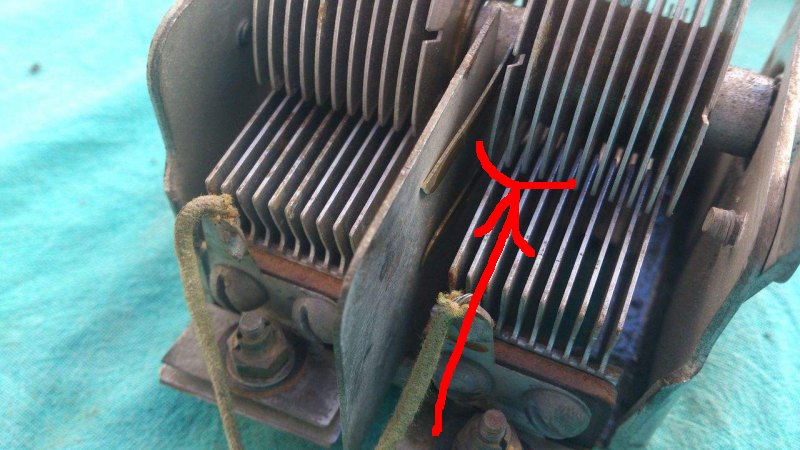
Apart from the horseshoe clips, these rotor plates need a bending tweak.
Posts: 178
Threads: 19
Joined: Feb 2014
City: The Motor City,Detroit MI
Hopefully, that's just an optical illusion in the photo. Continue looking to the left bank of plates. It looks like the circumference of the plates ends right there.
Posts: 16,488
Threads: 573
Joined: Oct 2011
City: Jackson
State, Province, Country: NJ
I think it is due to the photo angle. They look OK to me.
Posts: 29
Threads: 7
Joined: Aug 2014
City: España
The sheets are fine, it is the effect of the photograph.
I have cleaned the forks and facing down the defect.
[Image: http://s29.postimg.org/9pj1gs7pz/121.jpg]
Posts: 16,488
Threads: 573
Joined: Oct 2011
City: Jackson
State, Province, Country: NJ
Posts: 201
Threads: 26
Joined: Dec 2005
City: Morris Plains, NJ
(10-10-2014, 09:20 PM)morzh Wrote: Looks sparkling!
I know it would be a pain but I would grind off the rivets that hold the forks, clean all of the surfaces (especially the cap frame where the fork makes contact), and put it back together using screws. There's an awful lot of oxidation on the frame and it could make for a very noisy and intermittent tuning. A Dremel tool with a small grinding will quickly cut the rivets. The whole operation should take less than ten minutes.
Pete AI2V
Posts: 29
Threads: 7
Joined: Aug 2014
City: España
If the rivet is removed for cleaning, after it has become to be riveted.
[Image: http://s28.postimg.org/xtgp7sffh/DSC_0342_1.jpg]


![[-] [-]](https://philcoradio.com/phorum/images/bootbb/collapse.png)


