Starting 37-116 Deluxe Restoration
Posts: 7,297
Threads: 268
Joined: Dec 2009
City: Roslyn Pa
Tnx Nick, That's a really nice looking 37-116 122. I can attest to using mylar caps in the power supply. I used some small electrolytics in a model 87 about 2yrs ago. With regular use the caps lasted about 6 months and then shorted. Going to use mylars this time!! Have fun doing the restoration you have a great set when your done. It make the AM band sound like FM with it's broad selectivity and excellent audio frequency response.
Terry N3GTE
Posts: 126
Threads: 13
Joined: Sep 2013
City: Milwaukee, Wisconsin
Tonight I decided to tackle the 2 candhoms. So I desoldered the wires, labeling them as I did so, and drilled out the rivets.
One was a 2 section candohm (part 124 - 1k and 4k sections) where the 4k section opened up, and someone subbed in a 4k tubular ceramic. Surprisingly, they even did it the proper way with a new terminal strip, and didn't reuse the open terminal like many of the candohm repairs I have seen. The other one was behind it, and not easy to see until I got them out. It's a single section (part 118 - 14k) that still reads good.
However, I have never quite seen a casing like this on a candohm. Instead of the usual metal shell with fish paper around the resistor, its encased completely in black plastic, and has a metal strip around it to hold it in place. According to the part list, it's just labeled "Resistor (14,000 ohms, 1/2 watt)". This seems like a rather large package for just a 1/2 watt resistor. Given that it was a candohm, i just assumed I should go for a 10w replacement, despite the part list calling it 1/2w.
Not trusting the part lising of 1/2 watt for a candohm, I decided to replace it with 10w. 10w is usually my go to for candohms, as I don't want to power the radio on to find the voltage drop to calculate the actual power. So I go with 10w. It usually gives me enough of a safety/cooling factor as well.
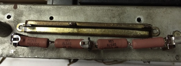
For the 14k resistor, I made up a replacement of two 7k 5w resistors in series to give me 10 watts of power handling (I figured 2 7k's in parallel would be just the right length, and a smaller diameter than a 10w 14k). You can obviously see how I made up the replacement, as I had temporarily screwed the terminal strips to it so I could get the spacing correct. I had angled the terminal strips to get me the proper horizontal spacing and height. And it's a good thing I did. one of the straps was behind the power transformer, so there wasn't much clearance. Luckily I was able to get a good enough angle, it cleared the transformer. Attached it to the chassis in the existing holes, and wired it back up.

For the multisection candohm, I took the same approach - 5w resistors in series for a combined 10w. I couldn't get the horizontal spacing exact for the terminals. But there was enough slack in the wires, and i hit the existing holes perfectly. So it worked out pretty well. Here is how I built it using the outside of the chassis. Since it's a downward shot, you can't see that I had screws in the chassis in the existing holes. That gave me a perfect way to align and solder everything. The terminal strip between the sections is currently floating however, as there is no hole there. I debated drilling one, but it really doesn't move much. The resistors and wires keep it steady. And it does it's job of preventing it from shorting against the chassis. There isn't anything near by that it could short on anyway. And it's not like monkeys are going to be banging on it and trowing it around. I could also get out my big Weller gun and solder it to the chassis wall too. Maybe I'll do that, just in case.
Posts: 126
Threads: 13
Joined: Sep 2013
City: Milwaukee, Wisconsin
My Solen caps arrived yesterday, so I decided to tackle the filter caps/cans tonight. Wow, are these suckers big! I had never re-stuffed a can before (I usually just disconnect the can and connect the new cap under the chassis), so I Googled some methods. I came across one where the guy in the video used a 3/4"PVC connector to hold the sections of the can together. So I decided to give that method a try.
The filters had been replaced before. I'm assuming the original style had the positive tab sticking out from the bottom. The replacements had wire leads coming out of them. So I cut the first can open with my Dremel. Pulled the short bottom off over the wires, and tried to figure out how to get the cap out of the top half. I had a H**l of a time getting all the stuff out. From what I can tell the cap was surrounded by a cardboard tube. Then they poured the tar in. Well the tar apparently leaked out of the tube and cemented it to the inside of the can. I probably spent 30 minutes slowly digging out chunks of cardboard, capacitor and tar. When i did the second one, i was surprisingly able to pull the tube out in one piece.
Now that I had the can apart, I soldered new lead wires to the cap and put on heat shrink. I know the cap is non-polarized, but I still put in a red and black lead for show. Then I looked at how I was going to put it together. The 3/4" PVC connector fit perfect in the can. And the Solen fit perfectly inside the connector. But that meant I had no way to get one of the leads out the bottom. So I grabbed my Dremel again and cut a slit in the connector for the wire to lay in.
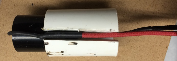
I wrapped some electrical tape around it to keep the wire in place when i slid it in the can. I tried putting it into the bottom piece, but the hole was too small as the insulation on my new wires is thicker. So I grabbed my drill and enlarged the hole to 1/4". The wires now fit through. I put the 2 halves together, and found the friction from the PVC connector was more than sufficient to hold them. Not to mention that is right where the card board insulator and clamp go. But I remembered my dad has some aluminum tape laying in my garage. So I cut a thin strip of it and went around the cut just to be safe. Here is the unexciting final product.

I slid the cardboard insulator back on, and it ripped. So I wrapped it on the outside with electrical tape and mounted it in the clamp. Then I tackled the second can, which went much easier. I feel like I should put some kind of note on the cans, so some day when I'm long gone and someone else has this radio, they know the work was done. And that these are film caps that probably won't need to be replaced the way electrolytics do. Or I can just not care and let that person figure it out.
I cut open and cleaned out the 8uF/10uF can. But I'm having trouble restuffing it. The rivet heads on the bottom that connect to the solder lug won't want to seem to take solder. So I'm not sure how to attach thew leads to them. Any suggestions in how to connect the new caps to the rivets/lugs?
(This post was last modified: 10-11-2014, 12:00 AM by Nick3092.)
Posts: 1,114
Threads: 14
Joined: Feb 2013
City: Irvington, NY
Drill little holes in the insulator adjacent to each terminal and pass each wire up through and solder to the respective lug. The rivets themselves are made of aluminum, so solder does not stick.
Posts: 126
Threads: 13
Joined: Sep 2013
City: Milwaukee, Wisconsin
(10-11-2014, 09:19 AM)Mondial Wrote: Drill little holes in the insulator adjacent to each terminal and pass each wire up through and solder to the respective lug. The rivets themselves are made of aluminum, so solder does not stick.
That method worked perfect. I put 3 holes in the insulator (2 positives and the negative that goes to CT).

Then I zip tied the two caps together, soldered the wires on, and they fit nicely in the coupler. Slid the wires in the new holes in the base, and here is the semi finished product.
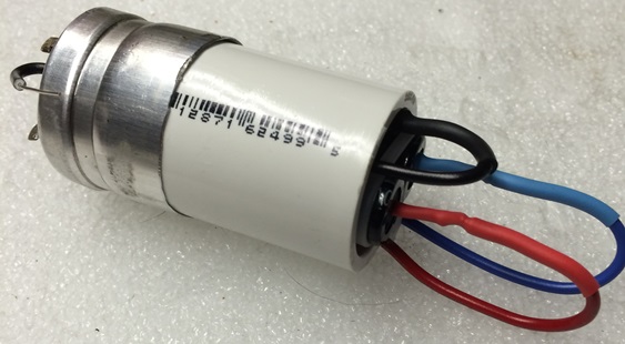
Then I attached the top of the can, slid the cardboard cover with the solder lug on, and it's ready to go back in.
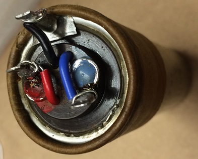
Did the same with the 3 cap can. On this one I tried running the negative side of the cap out the seam of the can, so it would get pinched and grounded to the clamp. But the tolerance was too tight. So I wound up having to bring a ground wire out for this one as well. I'll ground it to the open ground lug on the bakelite cap right above where this comes through the chassis. I had to drill the holes on this one on the lower outer lip, since with 3 rivets in the middle, there wasn't much room.
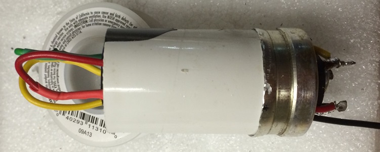
Now that I've tried it, I can say restuffing cans isn't the worst thing in the world.Although depending on how much tar and how stuck the innards are, it can be a real pain. It does make the underside of the chassis look a bit cleaner, and is almost a must on a low profile chassis like this one that doesn't have a lot of extra room to squeeze in 7 electrolytics.
I'm down to two more bakelite caps and a couple resistors in the the IF section of the chassis to replace. Then I need to remove the back cover to get to the terminal board along the back under the interstage transformer and replace the caps/resistors back there. After that, it's the part I've been dreading. Pulling the RF sub chassis to replace the parts in there.
I still also need to find out why the automatic tuning dial/hub doesn't turn when tuning via the vernier drive (but the tuning cap does). Like wise, when trying to use the automatic tuning presets, the dial moved, but the tuning capacitor doesn't move.
Posts: 162
Threads: 37
Joined: Oct 2012
City: St Louis MO USA
Finished one of these early this year and now working on another one right now. Bought mine from Willy in Pennsylvania and the cabinet was in beautiful condition. Yours looks as good as mine so good luck on the electronic restoration . Looks like your headed in the right direction and the right guys are paying attention .
Posts: 162
Threads: 37
Joined: Oct 2012
City: St Louis MO USA
Posts: 1,114
Threads: 14
Joined: Feb 2013
City: Irvington, NY
Nick, next time to make removing the insides from the electrolytics easier, heat the can with a heat gun. This will melt the tar and the insides will just slide right out.
Posts: 16,483
Threads: 573
Joined: Oct 2011
City: Jackson
State, Province, Country: NJ
I have an old wine cork screw, I screw it inside the cap stuffing, heat it with a heatgun, and then pull. The more you heat it the easier it is, just to hold it you might need a glove.
Posts: 126
Threads: 13
Joined: Sep 2013
City: Milwaukee, Wisconsin
Mondial Wrote:Nick, next time to make removing the insides from the electrolytics easier, heat the can with a heat gun. This will melt the tar and the insides will just slide right out.
morzh Wrote:I have an old wine cork screw, I screw it inside the cap stuffing, heat it with a heatgun, and then pull. The more you heat it the easier it is, just to hold it you might need a glove.
The corskscrew idea is neat. Although just the thought of heating it gives me flash backs of hot melted tar all over the first time I tried to restuff a bakelite block. My own fault for letting it get too hot. Since then, I found it's generally just as easy and less mess to chisel out the tar on the blocks using a small jewelers screwdriver. I can just vacuum up the solid chunks with my shop vac and clean out the remainder in the block with q-tips and thinner.
Well I think I now have all of the caps and resistors in the IF, power, and rear/audio sections replaced. I almost forgot about that capacitor pack on the top side in the IF section. I took that off and pulled the pack out of the can. I was able to remove the original wires fairly easily. In the past with these capacitor packs, I often put them on a small PCB. But this one was a pretty straightforward series connection, with a couple taps in between caps. So I found i could lay them all side by side, zip tie them together, solder the leads together, and then reattach the original wires to them.
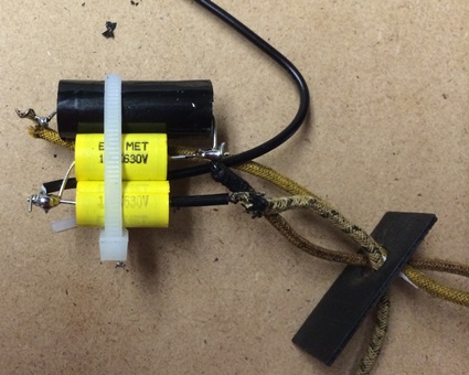
I then took the whole thing, wrapped it up in parchment paper (I figure that makes a decent insulator, considering is coated with silicone) folded the back end up and taped it to make a pouch, and slid it back in the can. The original pack had a ground wire soldered to the side of the can. But It only grounds through 2 litttle spring clips, and I'm not sure how much I trust that. So I ran a ground wire from the new pack I made out under the chassis and soldered it to a ground lug on a near by bakelite block.
The parts in the rear/audio section took me a bit longer than I anticipated. They shoved a fair amount of crap back there, and there was also a loom of wires laying right over everything. I couldn't take pictures to work off, because it was so cramped and I couldn't get a good angle. So I had to draw out my own little diagram and tracing what went where before even starting to work. Putting the new caps in was a little easier given their smaller size.
Tomorrow I have some things i need to do inthe morning, then sit down and watch the Packer game. Tomorrow afternoon/evening I'll take the rest of the "tower" off the front, so I can work on getting the RF chassis out to work on. Just the thought of that section is making me nervous. I was second guessing my work on the audio section as it is. That RF section looks like an even bigger mess.
Posts: 7,297
Threads: 268
Joined: Dec 2009
City: Roslyn Pa
Hey Nick nice work!! I've got two over here that need help.
Terry
Posts: 126
Threads: 13
Joined: Sep 2013
City: Milwaukee, Wisconsin
(10-12-2014, 01:30 PM)Radioroslyn Wrote: Hey Nick nice work!! I've got two over here that need help.
Terry
Thanks. Hopefully this thread will help someone else working on one of them. I'm not documenting all the basics. Just the odd stuff specific to this radio. Hopefully tonight I'll be able to document removing the RF sub chassis after the packer game and getting some household chores done. Luckily I have tomorrow off, so I can keep at it while everything is fresh in my mind.
Posts: 126
Threads: 13
Joined: Sep 2013
City: Milwaukee, Wisconsin
Well, I got the Front "tower" off, and then preceded to take out the RF sub chassis. You remove one screw on the back, and then lift the back up, pivoting on the front mounts. Once you get it high enough, it will come off the front. i desolderd the tuning cap so I could lay he chassis on the top, and took off the sides. That is when the horror set in.
Even with the sides removed and out of the chassis, this is a nightmare. There are two .05 caps (parts 9 and 28, i believe) that are actually inside the ring of coils. I have no idea how I am going to get them out. Another one is laying under the coils, connected to a ground lug in the middle, right under the coils. There are a couple of resistors there are no way I can even get to. Heck, I can't even test at least one of them to make sure it's in spec. I'm pretty sure Philco hated repairmen, and designed this chassis just to aggravate them.
I'm maybe 1/2 to 3/4 of the way done with the sub chassis. But I had to walk away and let me brain rest, so I can try and figure out how to get 9 and 28 out. If anyone who has replaced these two has suggestions, I'm open for them!
Posts: 16,483
Threads: 573
Joined: Oct 2011
City: Jackson
State, Province, Country: NJ
I was able to replace all caps in the RF Chassis without disconnecting or lifting it.
Took some patience.
One single cap I was not able to ground to the point where it was grounded originally, so I grounded it to the font part of the chassis.
One cap had a wire going inside jeld by a metal retainer I had to unbend and then bend back when I reinstalled the cap, usign a thick metal hook.
That was it.
No walk in the park, no, but no horrors either. Unless you choose to make it a horor yourself.
Just a big chassis with an RF section.
Posts: 126
Threads: 13
Joined: Sep 2013
City: Milwaukee, Wisconsin
(10-12-2014, 09:22 PM)morzh Wrote: I was able to replace all caps in the RF Chassis without disconnecting or lifting it.
Took some patience.
One single cap I was not able to ground to the point where it was grounded originally, so I grounded it to the font part of the chassis.
One cap had a wire going inside jeld by a metal retainer I had to unbend and then bend back when I reinstalled the cap, usign a thick metal hook.
That was it.
No walk in the park, no, but no horrors either. Unless you choose to make it a horor yourself.
Just a big chassis with an RF section.
There are two caps that I can't even fathom how you go to without taking it out. They are literally surrounded by coils.
Without taking the chassis out and removing the sides, you can barely even see them. Here is the approximate view (and about the only access point you would have had) if you didn't take out the RF chassis. You can barely see the end of the cap, as it is covered in coils and trimmers. If by some miracle, you could clip the lead on the visible end, I can't see how you would have got to the other end (that goes to a ground lug).
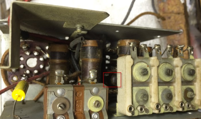
Even getting at it with the chassis removed, so don't really have any better access to it. This is a shot from the side, with the sides of the chassis removed. It's still pretty much inaccessible.
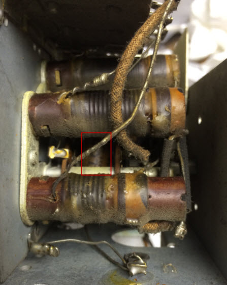
There is another cap in pretty much the exact same location in the bay next to it. I can't figure out any way to clip out the old one, let alone even get my soldering iron in there to apply the new one.
I'm open to any suggestion on how to tackle this one (and the one just like it in the next bay). I have far more access than you did right now, so it should be even easier for me to do it.
Users browsing this thread: 2 Guest(s)
|
|
Recent Posts
|
|
Need Help to ID this radio 11 tube Philco
|
| It is a 16B tombstone.morzh — 06:13 PM |
|
Zenith H725
|
| David - sorry, I reread your post and finally saw THD - now the % figures make sense. Thanks for explaining.
The PSU...EdHolland — 06:06 PM |
|
Need Help to ID this radio 11 tube Philco
|
| Hi Everyone,
New member but have been reading this for awhile for tips!
Vaccum tubes were before my time so bear with ...Ken D. — 06:03 PM |
|
My Philco 37-116 Restore
|
| Thank you MrFixR55, I appreciate your comments very much. I do not detect much hum if any so I will be staying with the ...dconant — 05:15 PM |
|
My Philco 37-116 Restore
|
| Hi DConant
Yes, you can replace chokes with resistors. You do stand the risk of increased hum. the solution is to inc...MrFixr55 — 04:23 PM |
|
Zenith H725
|
| 1.7-3.9 %, a modified Sine wave inverter is around 25%. Most generators from big box stores run 10% at a 50% load. What ...David — 04:06 PM |
|
My Philco 37-116 Restore
|
| I am having a heck of a time doing the alignment on the AM band. I can't seem to dial in the 1500 KC oscillator. I can h...dconant — 03:35 PM |
|
Zenith H725
|
| David - I think I understand but what units are you discussing (Low of 1.7, high of 3.9)?
Budget constraints for Ham ...EdHolland — 01:43 PM |
|
My Philco 37-116 Restore
|
| You're doing great.
I wish I could be more involved, but my mind is right now preoccupied with the reason I am here in ...morzh — 12:21 PM |
|
My Philco 37-116 Restore
|
| Hope you guys are still with me.
I have moved on to the alignment. I completed the IF alignment which was pretty muc...dconant — 10:47 AM |
|
Who's Online
|
There are currently 748 online users. [Complete List]
» 1 Member(s) | 747 Guest(s)
|
|
|

|
 
|


![[-] [-]](https://philcoradio.com/phorum/images/bootbb/collapse.png)


