Posts: 178
Threads: 19
Joined: Feb 2014
City: The Motor City,Detroit MI
I just started taking inventory under the chassis of my Philco 90 - single 47 version. I saw the notes on these two capacitors on the philcorepairbench site. It mentions 630 volt capacitors can be used in place of the paper 3 x .25 µf in 03325, despite the working voltage listed as 1200v under the metal case condenser page.
My question is on the 03327. Are 630v capacitors okay to use there as well, for the 1.0, .25, 0.1 µf capacitors? The working voltage is also listed as 1200v.
Posts: 16,495
Threads: 573
Joined: Oct 2011
City: Jackson
State, Province, Country: NJ
Kestas
Please, show the link to the sch and the position number, part number by itself (or whatever it is) is not informative.
Posts: 178
Threads: 19
Joined: Feb 2014
City: The Motor City,Detroit MI
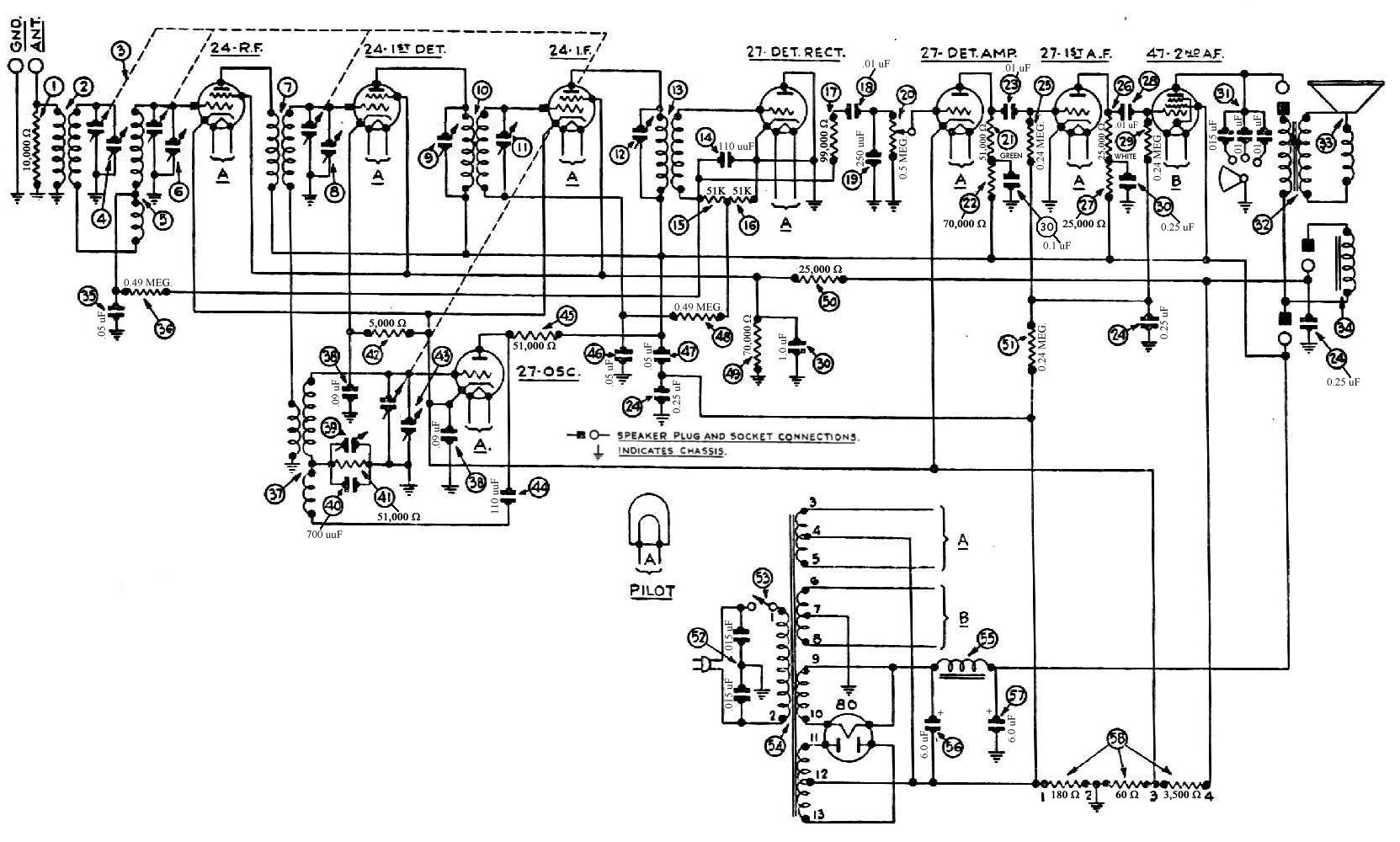
Here is the schematic. The three capacitors are labeled "30." They are presently housed in a metal case condenser.
Link to metal case condenser product information:
http://www.philcorepairbench.com/metalcap.htm
Link to information on Model 90 metal case condensers 03325 and 03327:
http://www.philcoradio.com/tech/90error.htm

(This post was last modified: 01-03-2015, 06:56 PM by
Kestas.)
Posts: 16,495
Threads: 573
Joined: Oct 2011
City: Jackson
State, Province, Country: NJ
All three are OK if 500V and up rated.
Posts: 178
Threads: 19
Joined: Feb 2014
City: The Motor City,Detroit MI
Thanks. How about the electrolytic capacitors - #56 and #57? They're both 6µf. The data sheet says they're rated at 400v. I've read lots of posts that say that electrolytic capacitors from Philcos from that era should be replaced with 500v capacitors, because 450v may not be enough.
Posts: 16,495
Threads: 573
Joined: Oct 2011
City: Jackson
State, Province, Country: NJ
Well....I always thought 450V would be enough but for about 2 seconds the voltage makes an excursion into 475-480V at which point the tubes start conducting and it drops down to about 300V.
So, yes - 500V rating takes all those questions off your mind.


![[-] [-]](https://philcoradio.com/phorum/images/bootbb/collapse.png)


