05-06-2016, 03:35 PM
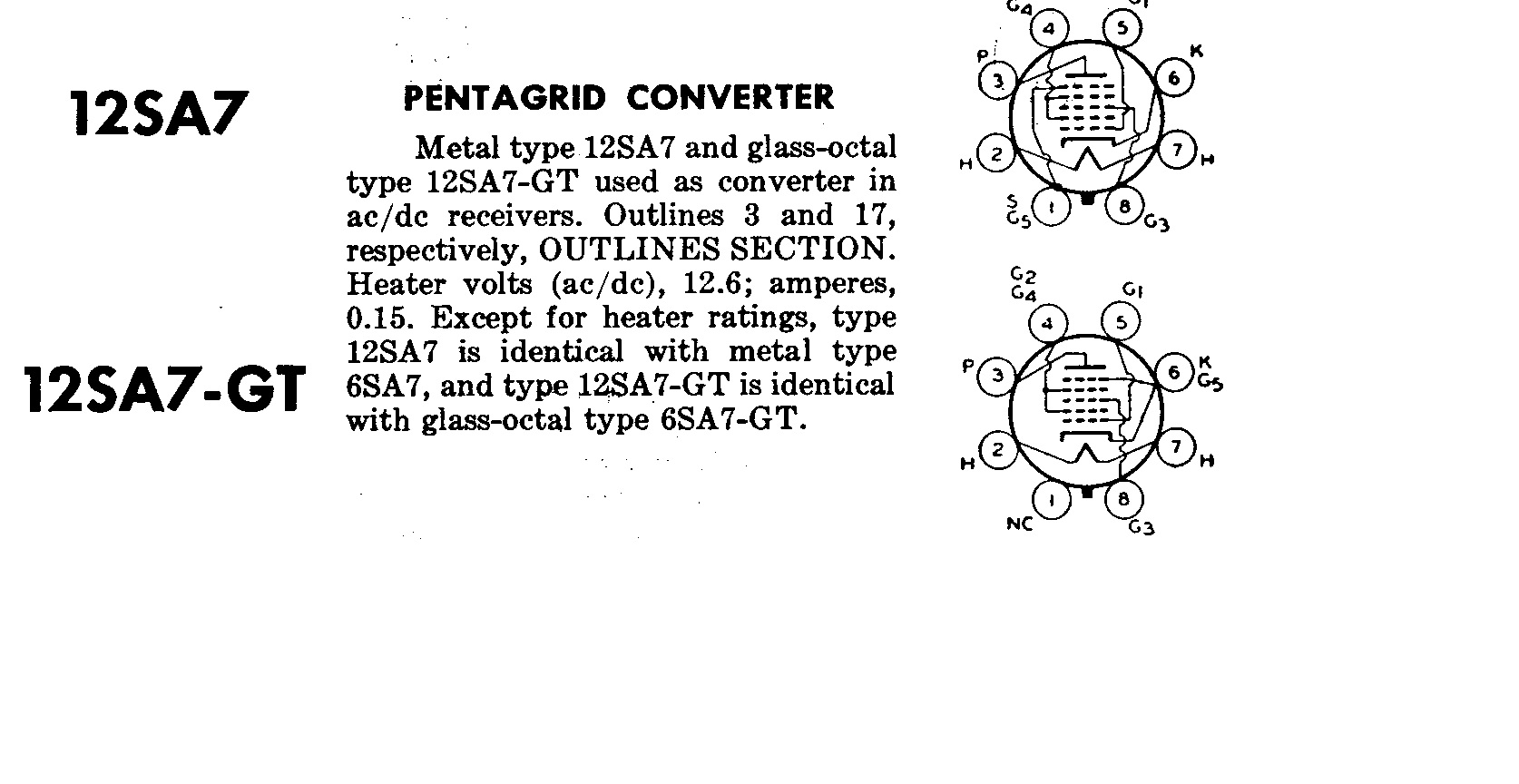
On most mixer/oscillator tubes (converter) the grid closest to the cathode is the oscillator, pin 5. Then the detector is going to be the grid that is between the 2 grids that are tied together, pin 8 between grids on pin 4.
On a lot of these tubes you can test the performance of the 2 parts separately, though they aren't really separate.

Speaking from my recent experience with crappy 6A7s.
If you are asking about the control grid (input) on the 12SK7 it is closest to the cathode. Pin 4.
You can always remember that on a pentode, one grid is going to be at or near the cathode voltage (near 0) and one grid (screen) is going to be at or near the plate voltage. So you can eliminate them as being the control grid (signal).
So your tuning stages will be on the control grid (input) and on the plate circuit (output).
On a lot of these tubes you can test the performance of the 2 parts separately, though they aren't really separate.
Speaking from my recent experience with crappy 6A7s.
If you are asking about the control grid (input) on the 12SK7 it is closest to the cathode. Pin 4.
You can always remember that on a pentode, one grid is going to be at or near the cathode voltage (near 0) and one grid (screen) is going to be at or near the plate voltage. So you can eliminate them as being the control grid (signal).
So your tuning stages will be on the control grid (input) and on the plate circuit (output).


![[-] [-]](https://philcoradio.com/phorum/images/bootbb/collapse.png)


