12-05-2017, 01:51 PM
Today I got around to dealing with a vexing problem with this radio. Right in the middle of the dial tuning there was a constant static crashing and no stations could be tuned in. I started by rechecking and re-doing the tuning capacitor pivot points (where the moving shaft is grounded). I tried new lubrication to no avail. Then I used Deoxit to clean those same points - no help. Next I checked between the isolated vanes and ground looking for intermittent shorting, but my digital meter just could not show the problem. I had put away my analog VOM, so I did not want to dig through the closet to find it. I took some silver CPU heat-sink compound and used some at each pivot point of the tuning capacitor shaft and the brass grounding clips. I used my Xacto knife blade to work it in between the clip surfaces and the tuning shaft. The radio was still acting up. Next I took a folded piece of paper and carefully cleaned between the moving vanes and stationary vanes of the tuning capacitor - still no help. I finally looked closely with a magnifying glass at the tuning vanes and noticed that the ones closest to the front of the radio seemed much closer together on the forward side than the back side of the vane to vane spacing. I wound up sliding my Xacto blade between the vanes and very gently moving the vanes slightly apart. When I stopped at each vane the distance appeared equal on each side of the moving vanes. I stopped for a recheck and I had cured the problem! Now the tuning capacitor has smooth tuning action from end to end.
Dealing with a tuning capacitor can be really frustrating and extreme care has to be exercised in working on them. At several points I was thinking I was going to have to buy a donor chassis to get a replacement tuning capacitor. Since I had reached that point of frustration with this one, I felt I had nothing to loose so I made the decision to try slightly bending each vane to get them centered vane-to-vane.
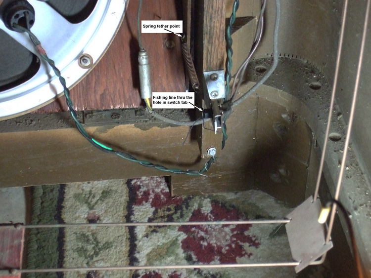
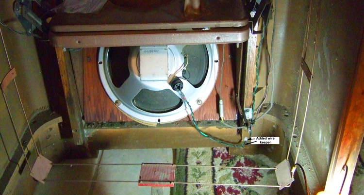
I mentioned in my last post about the speaker and phono compartment lamp wire lead dress in the cabinet. The speaker wires had been cut in two because they got caught between some of the steel levers associated with the phono compartment tilt-out feature. When I reinstalled the radio chassis in the cabinet I dressed the phono compartment lamp wires and the speaker wires in such a way that I could keep them away from the steel levers and the rotating AM Loop Antenna. There are some openings at the sides of the radio chassis mounting shelf in the cabinet which are at the leading edge and approximately the center on each side of that mounting shelf. I passed both sets of wires through the front opening on the left side of the cabinet (viewed from the front). I attached the lamp and its wires to the post at the middle above the tilt-out-door and the rest of that wire includes the spring loaded switch (which mounts near the bottom pivot point of the tilt-out door) was fastened at the position where it was originally secured. I repaired the broken/missing dial cord attached to the spring loaded switch using some braided nylon fishing cord. Here are some pictures of that area of the cabinet.


I thought this might help someone else deal with similar problems.
Joe
Dealing with a tuning capacitor can be really frustrating and extreme care has to be exercised in working on them. At several points I was thinking I was going to have to buy a donor chassis to get a replacement tuning capacitor. Since I had reached that point of frustration with this one, I felt I had nothing to loose so I made the decision to try slightly bending each vane to get them centered vane-to-vane.
I mentioned in my last post about the speaker and phono compartment lamp wire lead dress in the cabinet. The speaker wires had been cut in two because they got caught between some of the steel levers associated with the phono compartment tilt-out feature. When I reinstalled the radio chassis in the cabinet I dressed the phono compartment lamp wires and the speaker wires in such a way that I could keep them away from the steel levers and the rotating AM Loop Antenna. There are some openings at the sides of the radio chassis mounting shelf in the cabinet which are at the leading edge and approximately the center on each side of that mounting shelf. I passed both sets of wires through the front opening on the left side of the cabinet (viewed from the front). I attached the lamp and its wires to the post at the middle above the tilt-out-door and the rest of that wire includes the spring loaded switch (which mounts near the bottom pivot point of the tilt-out door) was fastened at the position where it was originally secured. I repaired the broken/missing dial cord attached to the spring loaded switch using some braided nylon fishing cord. Here are some pictures of that area of the cabinet.
I thought this might help someone else deal with similar problems.
Joe


![[-] [-]](https://philcoradio.com/phorum/images/bootbb/collapse.png)


