01-28-2018, 11:08 PM
OK - time for a progress report!
Filter Caps
My first step was to replace the replacement filter caps:
[Image: https://farm5.staticflickr.com/4660/2508...de81_z.jpg]
Lately I've switched to using large value film caps rather than modern electrolytics based on the advice I've read here. These are 400V rated caps (I bought these by mistake). I expect that's still OK for this radio since the original caps (not the replacements) were rated 400V (Part No. 4916). But next time I will buy 630V caps to be on the safe side for other models.
Anyway, here they are installed:
[Image: https://farm5.staticflickr.com/4765/2817...4105_z.jpg]
I used a 4-position terminal board to mount them.
Filter Choke
Next up that open filter choke.

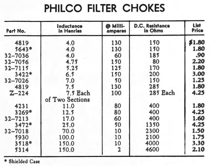
The original is Part No. 5643. So 4H, 130ma, 150ohm.
I have a model 90 parts chassis which uses the identically spec'd Part No. 4819. Unfortunately the filter choke had already been stripped.
Next best option: model 18 parts chassis. It uses a 32-7115 filter choke. It's pretty close - rated 5.25H, 125ma, 170ohm - hopefully close enough?
Anyway, I went with that. Physically the model 18 filter choke is very close to the original on the 112:
[Image: https://farm5.staticflickr.com/4623/3995...c4d0_z.jpg]
And installed:
[Image: https://farm5.staticflickr.com/4663/3905...fd51_z.jpg]
It's too cold to paint it right now - pretty will have to wait.
1st RF Coil
During my initial inspection I noticed a wire hanging from Part #2 first RF coil (the 10K resistor in parallel with the primary is already removed in the below pic).
[Image: https://farm5.staticflickr.com/4747/2608...13f0_z.jpg]
That there's your problem:
[Image: https://farm5.staticflickr.com/4612/3992...24c8_z.jpg]
There was just barely enough bit of the lead remaining to solder to. Full disclosure: in a stroke of brilliance I forgot to unsolder the other side of the primary coil before pulling it from the main form.
So both sides of the primary needed to be repaired. D'oh.
I drilled two 1/16" holes in the cardboard mounting piece to provide some physical stability for the new leads:
[Image: https://farm5.staticflickr.com/4720/2817...bbc4_z.jpg]
Installed back in the main coil form:
[Image: https://farm5.staticflickr.com/4615/2817...19ec_z.jpg] [Image: https://farm5.staticflickr.com/4697/2608...949d_z.jpg]
All back together - and it no longer measures open!
[Image: https://farm5.staticflickr.com/4752/3995...8b6e_z.jpg]
Test
I replaced the mouse-chewed wire, installed a set of tested tubes and connected everything up for a first test on the variac...
[Image: https://farm5.staticflickr.com/4769/2817...2d06_z.jpg]
And at around 90VAC... it lives!
Still lots more to do but an auspicious start.
Filter Caps
My first step was to replace the replacement filter caps:
[Image: https://farm5.staticflickr.com/4660/2508...de81_z.jpg]
Lately I've switched to using large value film caps rather than modern electrolytics based on the advice I've read here. These are 400V rated caps (I bought these by mistake). I expect that's still OK for this radio since the original caps (not the replacements) were rated 400V (Part No. 4916). But next time I will buy 630V caps to be on the safe side for other models.
Anyway, here they are installed:
[Image: https://farm5.staticflickr.com/4765/2817...4105_z.jpg]
I used a 4-position terminal board to mount them.
Filter Choke
Next up that open filter choke.
The original is Part No. 5643. So 4H, 130ma, 150ohm.
I have a model 90 parts chassis which uses the identically spec'd Part No. 4819. Unfortunately the filter choke had already been stripped.
Next best option: model 18 parts chassis. It uses a 32-7115 filter choke. It's pretty close - rated 5.25H, 125ma, 170ohm - hopefully close enough?
Anyway, I went with that. Physically the model 18 filter choke is very close to the original on the 112:
[Image: https://farm5.staticflickr.com/4623/3995...c4d0_z.jpg]
And installed:
[Image: https://farm5.staticflickr.com/4663/3905...fd51_z.jpg]
It's too cold to paint it right now - pretty will have to wait.
1st RF Coil
During my initial inspection I noticed a wire hanging from Part #2 first RF coil (the 10K resistor in parallel with the primary is already removed in the below pic).
[Image: https://farm5.staticflickr.com/4747/2608...13f0_z.jpg]
That there's your problem:
[Image: https://farm5.staticflickr.com/4612/3992...24c8_z.jpg]
There was just barely enough bit of the lead remaining to solder to. Full disclosure: in a stroke of brilliance I forgot to unsolder the other side of the primary coil before pulling it from the main form.
So both sides of the primary needed to be repaired. D'oh.
I drilled two 1/16" holes in the cardboard mounting piece to provide some physical stability for the new leads:
[Image: https://farm5.staticflickr.com/4720/2817...bbc4_z.jpg]
Installed back in the main coil form:
[Image: https://farm5.staticflickr.com/4615/2817...19ec_z.jpg] [Image: https://farm5.staticflickr.com/4697/2608...949d_z.jpg]
All back together - and it no longer measures open!
[Image: https://farm5.staticflickr.com/4752/3995...8b6e_z.jpg]
Test
I replaced the mouse-chewed wire, installed a set of tested tubes and connected everything up for a first test on the variac...
[Image: https://farm5.staticflickr.com/4769/2817...2d06_z.jpg]
And at around 90VAC... it lives!

Still lots more to do but an auspicious start.


![[-] [-]](https://philcoradio.com/phorum/images/bootbb/collapse.png)


