08-22-2018, 09:17 PM
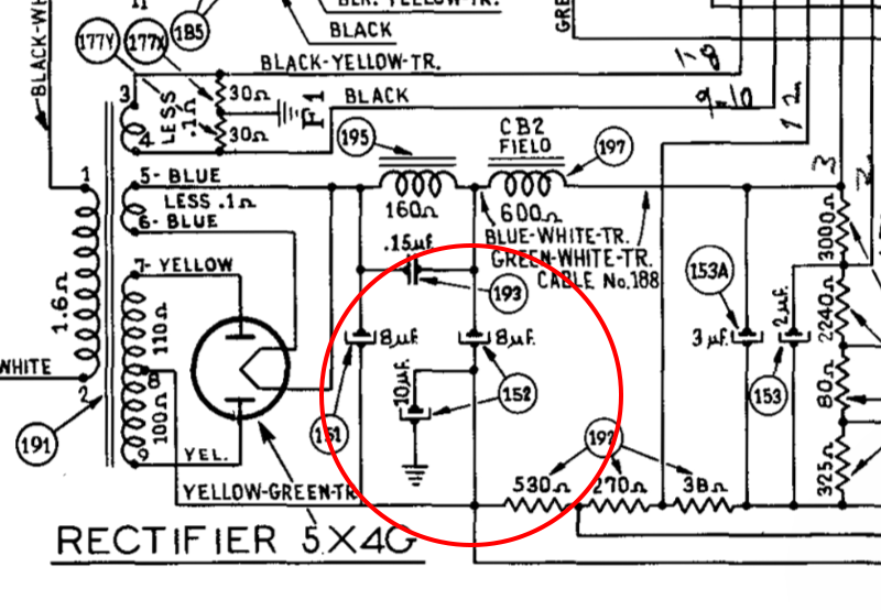
I have a question about the schematic from the 37-690 service bulletin (No. 267) and part 152.
Thats Part No. 30-2176, Electrolytic Condenser (8, 10 mfd).

When capacitors are drawn this way it usually means that the 'can' part is the negative and the 'stud' part is the positive.
I suspect the schematic is incorrect.
I believe that usually in this configuration the 10uF capacitor would have positive connected to ground., negative common with the other 8uF half of 152 and part 151 (another 8uF cap) all of which connects to the center-tap of the transformer.
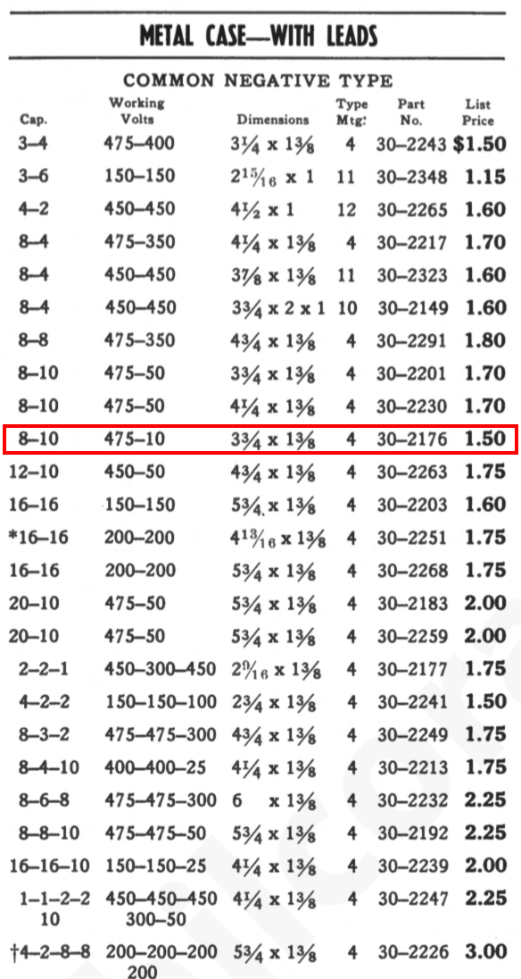
Another datapoint is that according to the 1939 Parts Catalog 30-2176 is 'common negative' with leads.

(Side note: it is nice to know that the 10uF section is rated at only 10V. There was no way I could fit both 8uF and 10uF Solen caps into the same can!)
Thats Part No. 30-2176, Electrolytic Condenser (8, 10 mfd).
When capacitors are drawn this way it usually means that the 'can' part is the negative and the 'stud' part is the positive.
I suspect the schematic is incorrect.
I believe that usually in this configuration the 10uF capacitor would have positive connected to ground., negative common with the other 8uF half of 152 and part 151 (another 8uF cap) all of which connects to the center-tap of the transformer.
Another datapoint is that according to the 1939 Parts Catalog 30-2176 is 'common negative' with leads.
(Side note: it is nice to know that the 10uF section is rated at only 10V. There was no way I could fit both 8uF and 10uF Solen caps into the same can!)


![[-] [-]](https://philcoradio.com/phorum/images/bootbb/collapse.png)


