01-08-2019, 01:27 PM
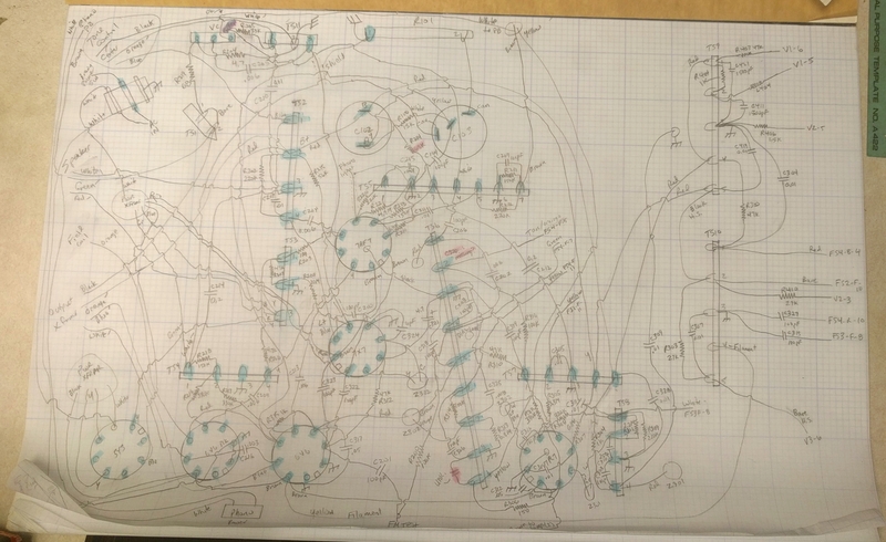
I've been racking my brain over a wiring issue in my 47-1230. Since I replaced all paper caps, electrolytics, and a whole bunch of resistors, I decided to check every single connection:

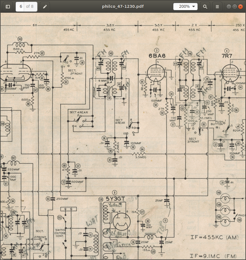
Looks like fun, huh? Everything checks out ok with one exception. I noticed this a while back, but dismissed it as being ok, but now I want to investigate it. There is either a mistake on the schematic, or I have a wire attached to the wrong terminal on the function switch. The solder looks original, and the way it's wired actually makes more sense to me than the way it's shown on the schematic. Here is the area I'm looking at (I generally prefer Philco's schematic, but in this case I think the Sam's is easier to see this issue):

Here's my interpretation of the schematic as drawn...I hope someone can tell me if I'm right or wrong. I'm looking at FS4-R, or as Sam's calls it, Sect 4 Rear. On the schematic, R89/C37 (47k/0.01) are connected to terminal 3 of the function switch. The function switch is shown in the pushbutton position. Clockwise it goes PB, BC, SW, FM. So in any position except FM, the top section of the IF can (the top section is used for FM) is bypassed and B+ (through R89) is connected to the top part of the AM winding of the IF can. But the bottom part of the primary just goes to terminal 4 of the function switch and nowhere else, so this winding would be useless, right?
But the way my radio is wired, R89/C37 are connected to terminal 4 of the function switch, and the only thing on terminal 3 is a wire going to the bottom of the FM winding/top of the AM winding in the IF can. To me this makes more sense and seems to be the way it should be. I'm hoping I'm wrong, but I do think my radio is wired correctly and the schematic is wrong.
Thanks for any help!
Rich
Looks like fun, huh? Everything checks out ok with one exception. I noticed this a while back, but dismissed it as being ok, but now I want to investigate it. There is either a mistake on the schematic, or I have a wire attached to the wrong terminal on the function switch. The solder looks original, and the way it's wired actually makes more sense to me than the way it's shown on the schematic. Here is the area I'm looking at (I generally prefer Philco's schematic, but in this case I think the Sam's is easier to see this issue):
Here's my interpretation of the schematic as drawn...I hope someone can tell me if I'm right or wrong. I'm looking at FS4-R, or as Sam's calls it, Sect 4 Rear. On the schematic, R89/C37 (47k/0.01) are connected to terminal 3 of the function switch. The function switch is shown in the pushbutton position. Clockwise it goes PB, BC, SW, FM. So in any position except FM, the top section of the IF can (the top section is used for FM) is bypassed and B+ (through R89) is connected to the top part of the AM winding of the IF can. But the bottom part of the primary just goes to terminal 4 of the function switch and nowhere else, so this winding would be useless, right?
But the way my radio is wired, R89/C37 are connected to terminal 4 of the function switch, and the only thing on terminal 3 is a wire going to the bottom of the FM winding/top of the AM winding in the IF can. To me this makes more sense and seems to be the way it should be. I'm hoping I'm wrong, but I do think my radio is wired correctly and the schematic is wrong.
Thanks for any help!
Rich


![[-] [-]](https://philcoradio.com/phorum/images/bootbb/collapse.png)


