03-01-2019, 07:14 PM
Ok, it's time for me to get back to this. First I need to apologize for jumping back and forth between the Philco schematic and the Sams schematic. In general I prefer working with the Philco schematic because I find it easier to follow. But the copy I have of the Sams schematic is clearer and easier to read. From here on I'll try to use just the Sams schematic when posting here.
I haven't done anything on the 47-1230 for the last 2 weeks or so, but I have done some research, studying, and thinking. I've watched a few videos and done some reading on tube theory and feel like I have a better understanding, but that hasn't helped me determine if I have a problem with too much current being drawn through the 15k, 2W resistor (R127). My current thinking is that the circuit is working as designed. Part of my reasoning is logic (albeit somewhat flawed logic), and part of it is wishful thinking. The wishful thinking is because I really want to call this radio done and surprise my Mom with it.
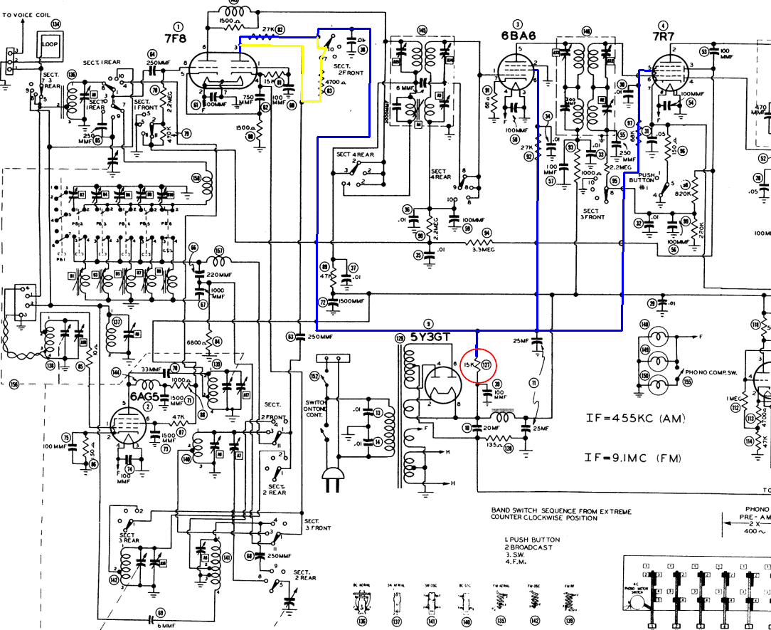
Here is my logic. As designed, R127 dissipates about 0.96W in AM mode, which is already higher than I would think they'd want to run a 2W resistor. But this is based on the voltages listed on the Philco schematic...310v on one side and 190v on the other, so 120v across the resistor. Simple math tells us that it's dissipating 0.96W. So now, if we assume that more current will be drawn through R127 in FM mode, then we will be running this resistor even hotter. Now here is where the 'flawed' logic may come in. My assumption is based entirely on the fact that my radio DOES draw more current through R127 in FM mode. I'm not smart enough to be able to tell from the schematic if it should draw more current in FM mode. Here is a schematic with the circuit in question highlighted in blue. The yellow section is switched into the circuit in FM mode. Basically, it connects a 4.7k resistor across the 27k resistor connected to the plate of the oscillator section of the 7F8, resulting in 4.004k.

I didn't find this current draw through R127 as a result of some in depth troubleshooting. Basically I just stumbled onto it. I noticed the voltage drop across it and did some math. I tried touching it the last time I worked on it after running in FM for a while and I couldn't hold my finger on it for more than a second.
Unless someone can convince me that there really is a problem here, I plan to replace the 15k, 2W resistor with a 15k, 5W resistor and button it up. But, if you are going to tell me there is a problem, please give me some guidance for determining what is causing the problem and how to fix it. What would you do?
Thanks,
Rich
I haven't done anything on the 47-1230 for the last 2 weeks or so, but I have done some research, studying, and thinking. I've watched a few videos and done some reading on tube theory and feel like I have a better understanding, but that hasn't helped me determine if I have a problem with too much current being drawn through the 15k, 2W resistor (R127). My current thinking is that the circuit is working as designed. Part of my reasoning is logic (albeit somewhat flawed logic), and part of it is wishful thinking. The wishful thinking is because I really want to call this radio done and surprise my Mom with it.
Here is my logic. As designed, R127 dissipates about 0.96W in AM mode, which is already higher than I would think they'd want to run a 2W resistor. But this is based on the voltages listed on the Philco schematic...310v on one side and 190v on the other, so 120v across the resistor. Simple math tells us that it's dissipating 0.96W. So now, if we assume that more current will be drawn through R127 in FM mode, then we will be running this resistor even hotter. Now here is where the 'flawed' logic may come in. My assumption is based entirely on the fact that my radio DOES draw more current through R127 in FM mode. I'm not smart enough to be able to tell from the schematic if it should draw more current in FM mode. Here is a schematic with the circuit in question highlighted in blue. The yellow section is switched into the circuit in FM mode. Basically, it connects a 4.7k resistor across the 27k resistor connected to the plate of the oscillator section of the 7F8, resulting in 4.004k.
I didn't find this current draw through R127 as a result of some in depth troubleshooting. Basically I just stumbled onto it. I noticed the voltage drop across it and did some math. I tried touching it the last time I worked on it after running in FM for a while and I couldn't hold my finger on it for more than a second.
Unless someone can convince me that there really is a problem here, I plan to replace the 15k, 2W resistor with a 15k, 5W resistor and button it up. But, if you are going to tell me there is a problem, please give me some guidance for determining what is causing the problem and how to fix it. What would you do?
Thanks,
Rich


![[-] [-]](https://philcoradio.com/phorum/images/bootbb/collapse.png)


