03-04-2019, 10:40 PM
So...
Since my last post, I have received 330 ohm resistors, a couple NOS TCG (NTE) 1230 multiplex decoder ICs, and some 16 pin DIP IC sockets.
This evening, I finally felt good enough to get back to the Marantz boards.
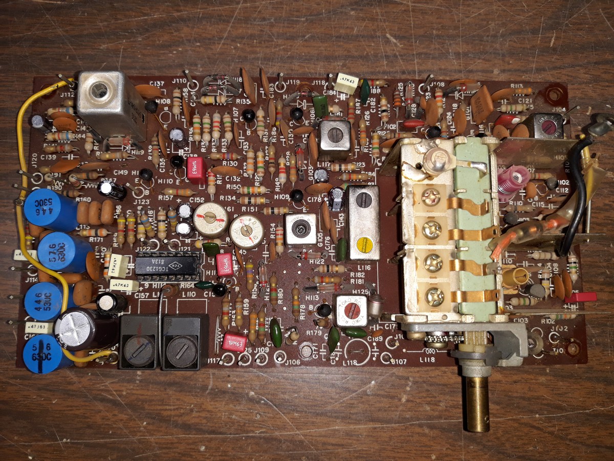
In short order, I had removed the original LA3310 multiplex decoder IC and replaced it with a 16 pin DIP IC socket and a NOS TGC (NTE) 1230 IC.
I wanted to use the socket to make any future replacement of the IC nice and easy. I had read that this IC may have been the cause of loss of FM in the original tuner board, so I wanted to make sure the IC in this board was replaced. I did the same thing in a Lafayette solid state receiver I have. Adding a DIP IC socket did no harm to the receiver, it works fine and if replacement of the IC is ever needed, it will be a breeze (assuming the IC is still available in that future time).
The tuner board is now ready for installation in the 4230.

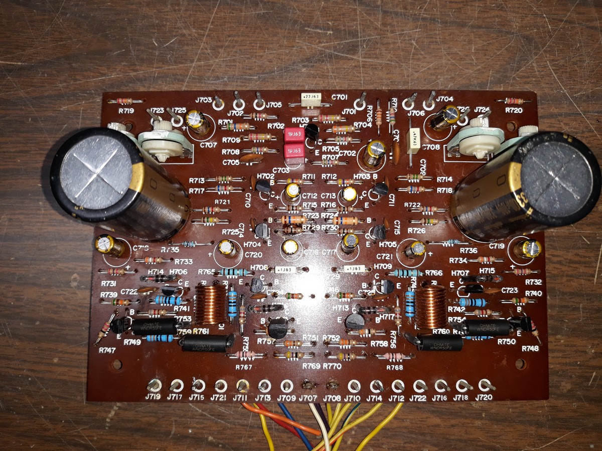
Then, I turned my attention to what will be the replacement left channel audio output board.
I stuffed it with 330 ohm resistors. I found that I had forgotten to install two 10 ohm resistors; these, too, were installed.
The board itself is now ready.

All that remains is to replace the audio output transistors and wire them into the left channel audio output board.
Then comes the fun of pulling the current left channel audio output assembly and replacing it with this one, removing and resoldering about a million wires in the process. Then lather, rinse and repeat for the tuner board.
Keeping fingers crossed...
P.S. I plan to rebuild the original tuner board in the same manner as I did this one, in case I ever need it. I have so much time and $$$ tied up in this Marantz that I would never get a fraction of it back, so it's a keeper.
Since my last post, I have received 330 ohm resistors, a couple NOS TCG (NTE) 1230 multiplex decoder ICs, and some 16 pin DIP IC sockets.
This evening, I finally felt good enough to get back to the Marantz boards.
In short order, I had removed the original LA3310 multiplex decoder IC and replaced it with a 16 pin DIP IC socket and a NOS TGC (NTE) 1230 IC.
I wanted to use the socket to make any future replacement of the IC nice and easy. I had read that this IC may have been the cause of loss of FM in the original tuner board, so I wanted to make sure the IC in this board was replaced. I did the same thing in a Lafayette solid state receiver I have. Adding a DIP IC socket did no harm to the receiver, it works fine and if replacement of the IC is ever needed, it will be a breeze (assuming the IC is still available in that future time).
The tuner board is now ready for installation in the 4230.
Then, I turned my attention to what will be the replacement left channel audio output board.
I stuffed it with 330 ohm resistors. I found that I had forgotten to install two 10 ohm resistors; these, too, were installed.
The board itself is now ready.
All that remains is to replace the audio output transistors and wire them into the left channel audio output board.
Then comes the fun of pulling the current left channel audio output assembly and replacing it with this one, removing and resoldering about a million wires in the process. Then lather, rinse and repeat for the tuner board.
Keeping fingers crossed...
P.S. I plan to rebuild the original tuner board in the same manner as I did this one, in case I ever need it. I have so much time and $$$ tied up in this Marantz that I would never get a fraction of it back, so it's a keeper.
--
Ron Ramirez
Ferdinand IN


![[-] [-]](https://philcoradio.com/phorum/images/bootbb/collapse.png)


