Thread Rating:
  • 0 Vote(s) - 0 Average
  • 1
  • 2
  • 3
  • 4
  • 5

Scott Marine Radio
#8

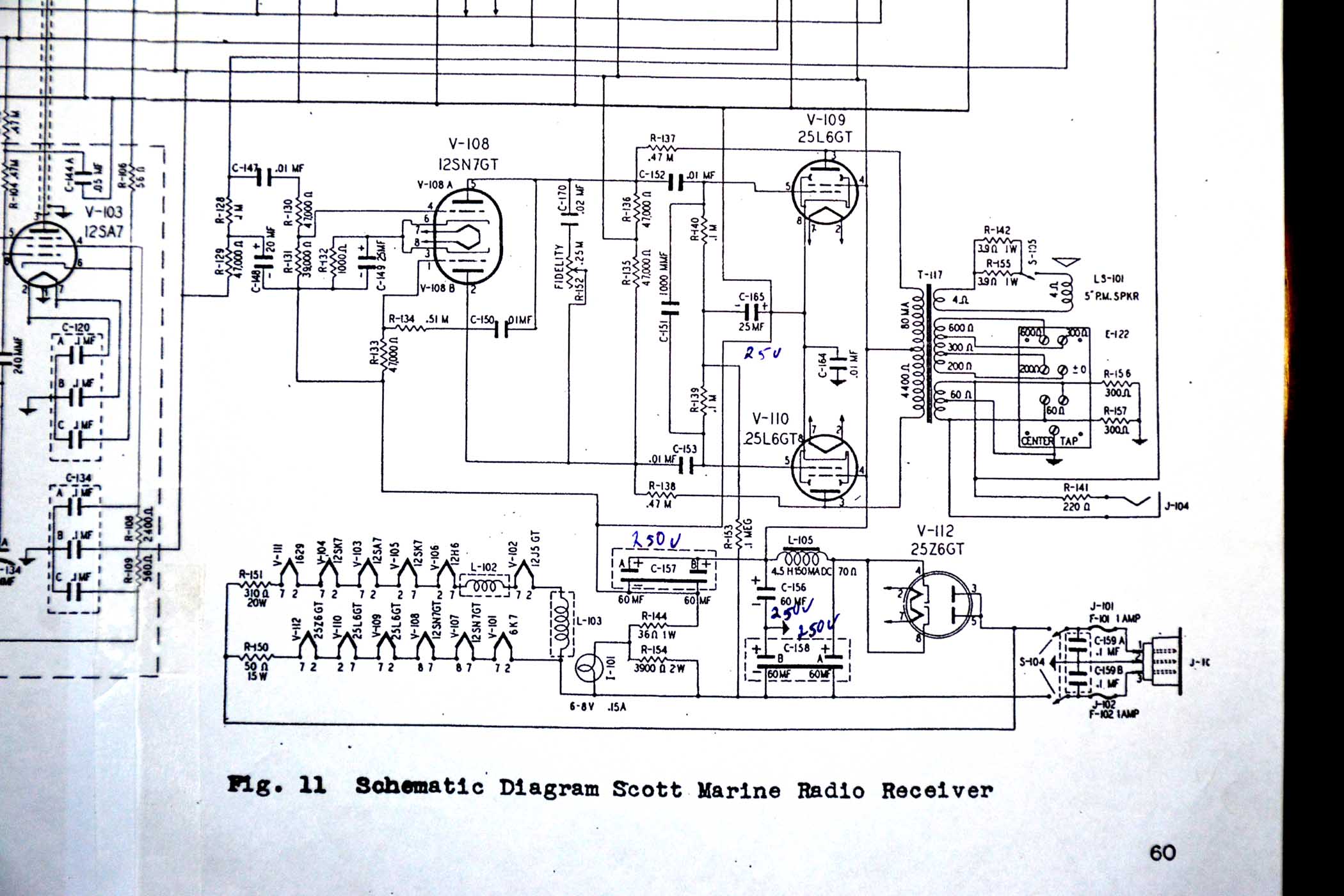
That looks like a bit more extensive of a radio than mine.  maximum DC voltage in this thing is about 120 volts so the electrolytic cans were rated at 200 volts.  Most of the sections were 60mfd.  I used 60 mfd Nichicon's rated at 250 volts.  I purchased the caps with the longest life and highest ripple voltage capability.  This radio uses a ground buss that is separate from the chassis ground.  Chassis ground runs abut 7 to 10 volts negative compared to the ground buss (I can vary that voltage by changing the pilot lamp) and this provides the grid bias for the 25L6's.  The ground buss is the negative side of C-157.  The negative line is the neutral of the AC in.  Notice C-158.  The A partition is the first filter cap for the half wave rectifier.  The B portion filters the chassis ground to negative line.  One would think that chassis ground would be riding some small positive voltage above the negative line.  It does not.  Chassis ground is about .05 volts negative from the negative line, putting C-158B slightly in reverse polarity mode  Very slightly.  When I turn the radio off, that voltage jumps to about 20 volts reverse polarity and then slowly dissipates.  I get a little concerned about what this reverse polarity will do to the cap over time.  Interestingly, there was a 47k resistor across this cap that is not on the schematic, nor is it called out on the chassis  as every other component is.  I wonder if that resistor was added reduce the effect of the reverse polarity.

Any ideas from some of you EE people who can analyze the design better than I can?


Messages In This Thread
Scott Marine Radio - by rfeenstra - 04-01-2019, 11:32 PM
RE: Scott Marine Radio - by rfeenstra - 04-05-2019, 12:19 AM
RE: Scott Marine Radio - by Eliot Ness - 04-05-2019, 08:16 AM
RE: Scott Marine Radio - by Ron Ramirez - 04-05-2019, 08:20 AM
RE: Scott Marine Radio - by rfeenstra - 04-05-2019, 10:54 AM
RE: Scott Marine Radio - by rfeenstra - 04-10-2019, 12:52 AM
RE: Scott Marine Radio - by Phlogiston - 04-10-2019, 01:30 PM
RE: Scott Marine Radio - by rfeenstra - 04-10-2019, 08:54 PM
RE: Scott Marine Radio - by rfeenstra - 04-11-2019, 06:43 PM
RE: Scott Marine Radio - by rfeenstra - 06-20-2019, 02:50 PM
RE: Scott Marine Radio - by Eliot Ness - 06-20-2019, 03:42 PM
RE: Scott Marine Radio - by Ron Ramirez - 06-20-2019, 07:50 PM


Users browsing this thread: 1 Guest(s)
[-]
Recent Posts
Shadow Meter Bulb
Phorum members, I am trying to find the bulb # for PHILCO Shadow Meter part number 45-2180 that is from a 37-640 chassis...georgetownjohn — 06:53 PM
Philco 41-608 changer coupler
3D-printing...short of machining, of course. Or molding.morzh — 05:20 PM
Philco 41-608 changer coupler
Thanks, Morzh. That solves the issue of the rubber pieces. Now, I need to find a way to replicate the pot metal piec...alangard — 05:07 PM
12' Philco
If it is 12', either Kareem or Andre would have to jump pretty high to look at the front panel. Kareem would have an e...morzh — 01:48 PM
12' Philco
And here's a story about the tires on the truck. Same "no-stoop" guy must have installed these! Take care a...GarySP — 01:17 PM
Hickok AC51 tube tester
I think they have only shown the secondaries of the transformer. Two of them feed the rectifiers' filaments.morzh — 12:58 PM
IF can wire size and Rubber mounts?
Arran If the wire inside cans is the gauges you mentioned, the sole reason for that would be mechanical, to stiffen t...morzh — 12:56 PM
12' Philco
Rod, Yes, I know, but the Giant Philco is not around anymore either, so I go by whoever was alive fairly recently. H...morzh — 12:54 PM
Hickok AC51 tube tester
Absolutely no one is going to reverse engineer that circuit. Even the iron core is missing.RodB — 10:37 AM
IF can wire size and Rubber mounts?
Thanks to both members for your help regarding wire and tuner mtg supports. regards--Johngeorgetownjohn — 09:33 AM

[-]
Who's Online
There are currently 4867 online users. [Complete List]
» 1 Member(s) | 4866 Guest(s)
Avatar

>