Posts: 1,393
Threads: 46
Joined: Nov 2017
City: Menlo Park
State, Province, Country: CA
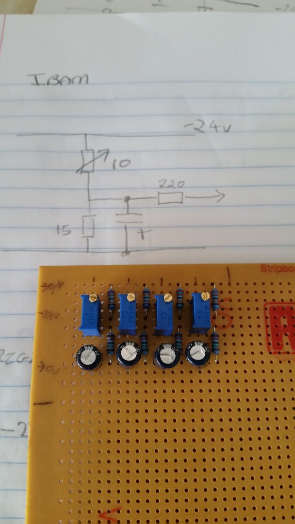
Progress today, I figured out the picky perfboard pot placement problem, to get a layout and footprint of components that I like. It also makes sense in relation to the position of the output valves. Also, I chose carefully so that clockwise rotation of the trimmer will decrease the bias voltage, increasing the bias current. That makes most sense to me, turn the dial clockwise to get a bigger reading of the voltage on the cathode resistor.
Here's the board, ready to be cut down and wired in:

Wires to the o/p section will attach at the top of the board, for neat routing around the chassis. Feed from the -24V bias supply will attach to the left edge.
Am starting to feel much happier about how this will turn out.
The board will get a dry run, just to see that the voltages are correct, and adjustable, before tying it in to the circuit proper.
Cheers
Ed
I don't hold with furniture that talks.
Messages In This Thread
RE: Fisher 500C restoration - by EdHolland - 07-14-2019, 11:02 PM
Users browsing this thread: 1 Guest(s)
|
|
Recent Posts
|
|
1949 Motorola 5A9M
|
| This would be the second portable in the "other radios" forum where I have a similar one in my collection. I h...Arran — 12:41 AM |
|
Looking for any info: 1977 Ford-Philco Console Hi-Fi Turntable and Radio
|
| Hi PittsburgTost.
The record changer looks like a Garrard or BSR (Likely Garrard). The spindles just pull out and pu...MrFixr55 — 11:57 PM |
|
Looking for any info: 1977 Ford-Philco Console Hi-Fi Turntable and Radio
|
| Hello PittsburghToast ,
Welcome aboard and it looks like gary may have something for you !
now if I dig through my se...radiorich — 11:35 PM |
|
Model 80 Antenna Issue?
|
| You are kind of on the right path. You can touch the grid cap of the Detector/Oscillator 36 tube. I'm expecting a respon...RodB — 08:48 PM |
|
Looking for any info: 1977 Ford-Philco Console Hi-Fi Turntable and Radio
|
| Welcome to the Phorum, PittsburghToast! I found an old thread that my interest you regarding the quality and worth of P...GarySP — 08:48 PM |
|
Looking for any info: 1977 Ford-Philco Console Hi-Fi Turntable and Radio
|
| Welcome to the Phorum!
:wave:
We do not have anything on that unit in our digital library. There is a Sam's Photof...klondike98 — 08:47 PM |
|
Model 80 Antenna Issue?
|
|
I’ve replaced all the caps and resistors and the radio is working but minimal volume unless I put my hand near the re...Hamilton — 08:24 PM |
|
Looking for any info: 1977 Ford-Philco Console Hi-Fi Turntable and Radio
|
| Hi there! this is my first time posting. I recently picked up this Ford-Philco Console record player and radio at a yard...PittsburghToast — 07:28 PM |
|
philco predicta
|
| I found that where I have the 140v B+ there is 50v and the tuner receives 235v through the orange cablecgl18 — 04:14 PM |
|
Philco 91 code 221
|
| Chassis grounds thru rivets is another good place to look. Oh and the stator screws on the tuning cap where the leads at...Radioroslyn — 08:11 AM |
|
Who's Online
|
| There are currently no members online. |

|
 
|


![[-] [-]](https://philcoradio.com/phorum/images/bootbb/collapse.png)


