09-10-2019, 09:13 PM
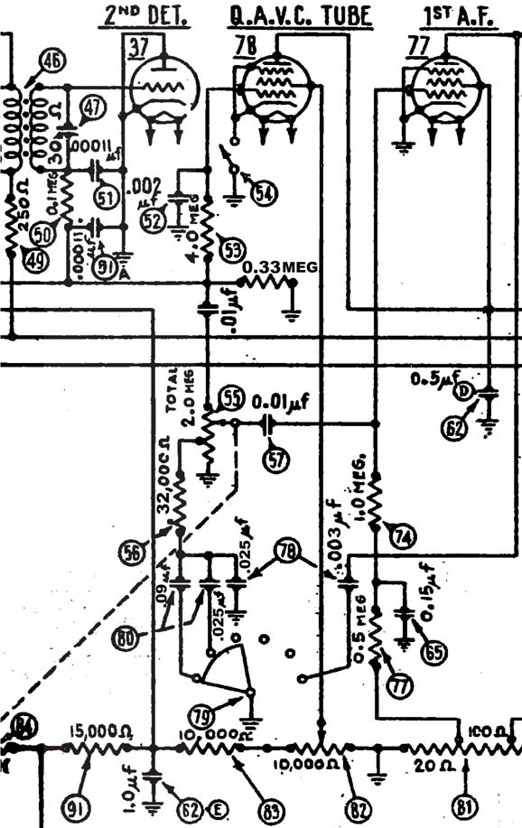
So, I've been slowly reinstalling components, re-stuffing bakelite caps, and hooking things up again. I check my work with the schematic and a zillion pics I take. I have run across a real question about the tone control. I've looked at Ron's post about the three tone circuits that were used and studied the documentation on factory changes. I have what Ron calls the second version. Looking at the schematic you would expect the following:
There are 4 caps involved, a .09, 2 - .025's, and a .003. The .09 and the .003 are located in the tone control itself. The 2 .025's are in a bakelite block. One of the .025 caps is always in circuit.
You would expect that in position 1 as shown in the schematic , the .09, and both .025's are connected. In position 2, the .09 is taken out and the 2 .025's are in the circuit. In position 3, only the permanently connected .025 is in the circuit. Position 4 switches in the .003 which is connected to the plate circuit of the 1st AF, reducing treble. All is good.
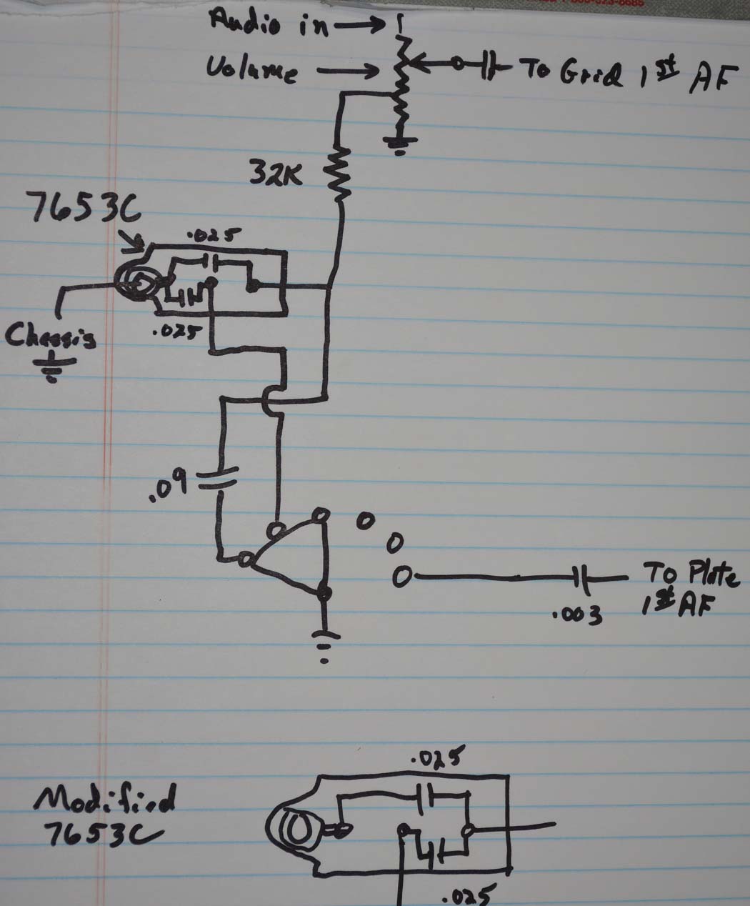
The 2 .025's are actually in a 7653C capacitor block. This is confirmed by what is in my radio, and by the Philco listed changes to the 16. The design of the 7653C ties one end of both .025's to ground (see my drawing of how it was hooked up in my 16B.) In this configuration, one of the .025 caps is really never in the circuit. It's either shorted or open and does nothing for bass compensation. Positions 2 and 3 of the switch would produce exactly the same result. The only way it would work as the schematic suggests is to modify the 7653C as I show in the drawing. Am I missing something here? Is the drawing for the 7653C incorrect in the "Philco Condensers and More" book? That's where I got the layout for the cap block.
Also, for information only: The Rider schematic for the 16 is missing the connection from the screen grid to the plate of one of the push pull output 42's. I believe it is correct in the Philco Phorum Resources.


![[-] [-]](https://philcoradio.com/phorum/images/bootbb/collapse.png)


