10-31-2019, 09:37 PM
So I spent my Halloween doing some work to my T8-14.
I began by winding a 100 turn coil onto a toilet paper roll in preparation for giving this set an alignment. The plan is to connect the signal generator to the coil, and then wind a few turns of wire around that winding to couple to the radio.
The next job was to remove the old, worn out dial scale.

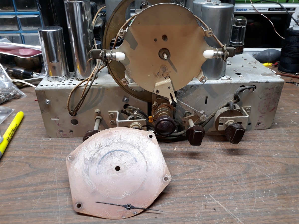
At first I thought the pointer was held in place by a tiny screw in its center. It certainly appeared as such. But after my tiniest screwdriver would not budge the "screw", I did a quick web search. I found that that isn't a screw at all but merely part of the slotted end of the shaft to which the dial pointer is fastened - it is simply pressed on. So I removed it by carefully pulling it off with a pair of needle nose pliers. Then, after removal of the four push pins (for lack of a better term) which held the dial scale in place, it looked as shown in the photo above.
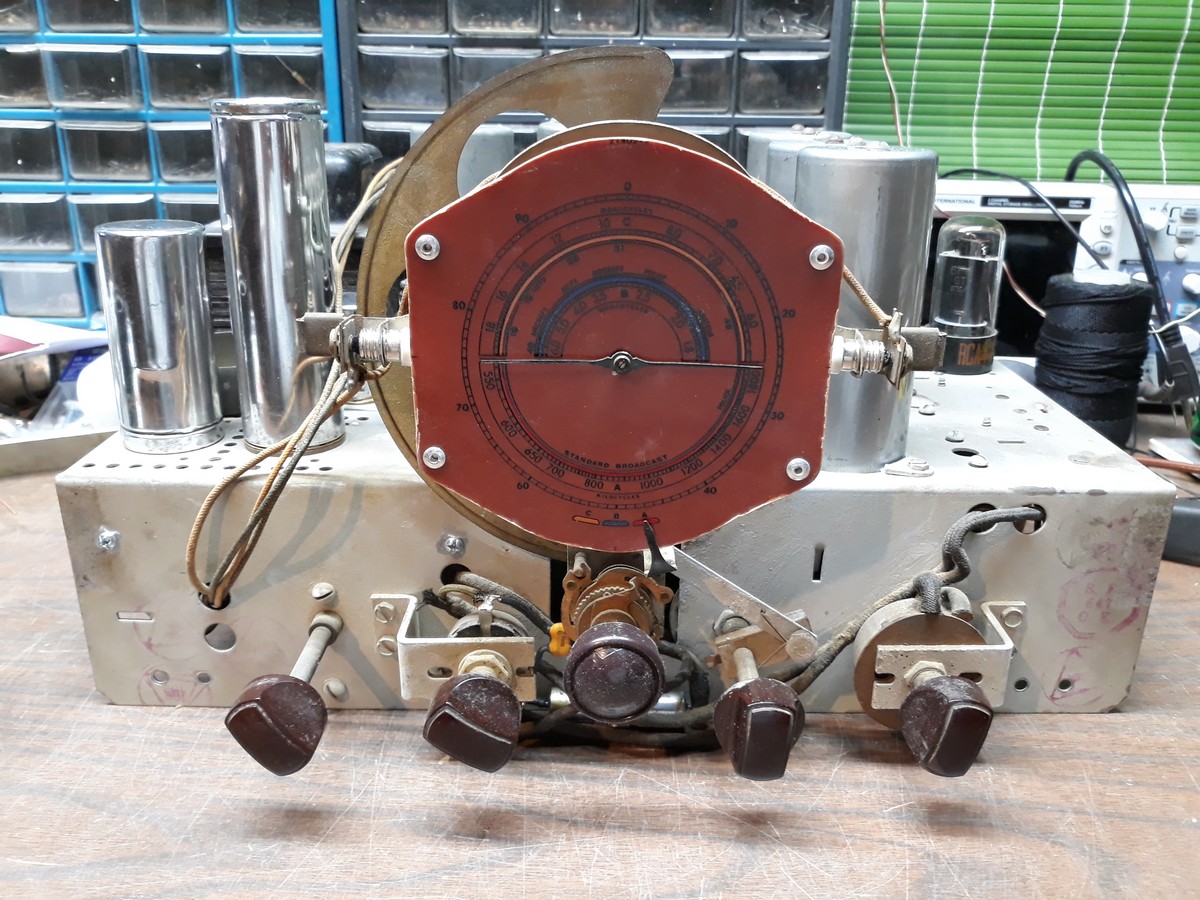
And then, it was time to cut out the new dial scale. Yes, the dial scale I bought was uncut and undrilled. The plastic is very thick and hard also, and was quite hard to cut. But I finally managed to get the job done. Drilling holes was the easy part. Finally, I attached it to the dial face with pop rivets.
Here is how it looks now.

The original dial did not have the 0 to 90 scale around the perimeter of the dial. But the frequencies are the same, so it works for me. I have since learned this is actually the proper scale for a T10-1 or C8-15. Oh well. As I said, the frequencies are exactly the same.
After I took the photo, I noticed that I didn't get all of the dust off the dial scale left from drilling the holes. That was quickly taken care of with a tissue.
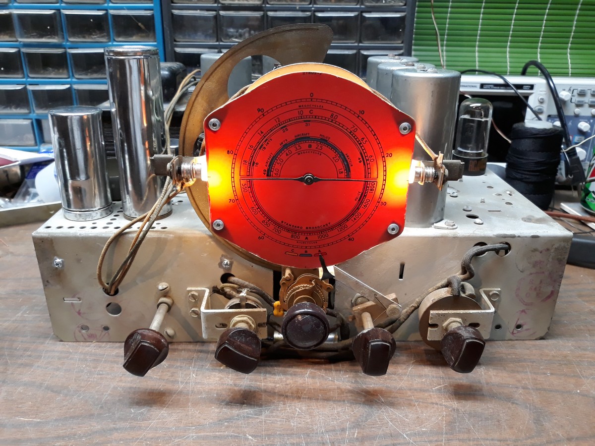
I pulled the rectifier tube, plugged the radio in, and turned it on just to see the dial illuminated.

The photo makes the areas where the dial lamps are located look much "hotter" than they really are. Blame my cellphone camera.
So now it is ready for the alignment which is to come tomorrow evening or Saturday.
I began by winding a 100 turn coil onto a toilet paper roll in preparation for giving this set an alignment. The plan is to connect the signal generator to the coil, and then wind a few turns of wire around that winding to couple to the radio.
The next job was to remove the old, worn out dial scale.
At first I thought the pointer was held in place by a tiny screw in its center. It certainly appeared as such. But after my tiniest screwdriver would not budge the "screw", I did a quick web search. I found that that isn't a screw at all but merely part of the slotted end of the shaft to which the dial pointer is fastened - it is simply pressed on. So I removed it by carefully pulling it off with a pair of needle nose pliers. Then, after removal of the four push pins (for lack of a better term) which held the dial scale in place, it looked as shown in the photo above.
And then, it was time to cut out the new dial scale. Yes, the dial scale I bought was uncut and undrilled. The plastic is very thick and hard also, and was quite hard to cut. But I finally managed to get the job done. Drilling holes was the easy part. Finally, I attached it to the dial face with pop rivets.
Here is how it looks now.
The original dial did not have the 0 to 90 scale around the perimeter of the dial. But the frequencies are the same, so it works for me. I have since learned this is actually the proper scale for a T10-1 or C8-15. Oh well. As I said, the frequencies are exactly the same.
After I took the photo, I noticed that I didn't get all of the dust off the dial scale left from drilling the holes. That was quickly taken care of with a tissue.
I pulled the rectifier tube, plugged the radio in, and turned it on just to see the dial illuminated.
The photo makes the areas where the dial lamps are located look much "hotter" than they really are. Blame my cellphone camera.
So now it is ready for the alignment which is to come tomorrow evening or Saturday.
--
Ron Ramirez
Ferdinand IN


![[-] [-]](https://philcoradio.com/phorum/images/bootbb/collapse.png)


