05-13-2020, 11:00 PM
After a diversion restoring a 6-D-539 chassis I'm back to the 37-116.
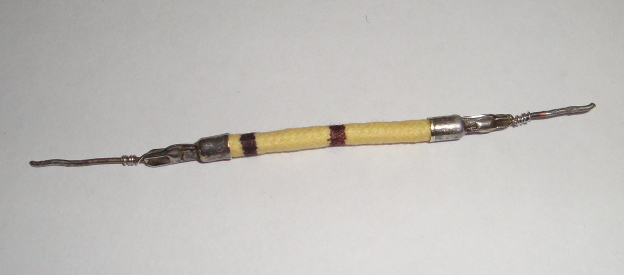
Since I'm re-stuffing the capacitors it seemed like a sin not to "re-sutff" the bad, flexible 400 ohm, 1/2W resistor in the RF chassis. The original's resistance read quite high and varied as I "wiggled" it.
The insulation was gotten from some Radio Daze some cloth covered. It has PVC(?) insulation inside and the insulated wire pulls out easily. The resistor inside is 4x 100 ohm, 1%, 1/4W resistors. I drilled small holes in the end caps to pass the new resistor leads out to the original, external leads. I think the end caps are aluminum and didn't trust soldering to them. I added a couple bands with markers and that was that. However I wouldn't want to flex it much. The 1/4W resistor wires are pretty fragile.
Considering nobody will ever see this buried in the RF chassis I'm starting to think I'm nuts...
It looks like the original hair thin, nichrome(?) wire was passed through the end of the caps and crimped with the external leads.
Can't think of anything witty.
Greg O.
Whitehall, PA


![[-] [-]](https://philcoradio.com/phorum/images/bootbb/collapse.png)


