08-04-2020, 08:47 PM
I have refrained from picking up any radios for quite a while now, but a month or so back I splurged and picked up a little export AC/DC RCA Q10. (It was cheap. Keep that word in mind...cheap...as you read on.)
It had its issues (don't they all). This one was missing its safety interlock and has no back. I resolved the interlock issue by cutting a piece of plastic and creating my own entrance point for the AC cord. I drilled two holes in the plastic and ran the separated zip cord through the holes, tying the wires in an Underwriters' knot inside the chassis.
It's an unbelievably cheap radio. And it is a hot chassis set! Yes, one side of the AC line connects directly to the chassis. It does play quite well after a recap, though.
But I digress.
I started aligning the set this evening. All went well until I got to the first SW alignment step - the 18 mc oscillator adjustment. As I turned the trimmer screw, I suddenly realized that there was no resistance. The screw was stripped! More accurately, the screw itself was fine, but the Bakelite panel into which the screw had been threaded was stripped.
Talk about a cheap way to build a variable capacitor...I find it hard to believe that RCA, which built quality stuff before WWII, became so cheap immediately postwar.
So I am in a dilemma.
The only option I can think of is to do away with the movable plate of the original trimmer and install a separate trimmer capacitor to replace it.
But I thought I would ask the opinions of my esteemed colleagues here first before proceeding. (Actually, I won't be doing anything more to it for a few to several weeks.)
What say you?
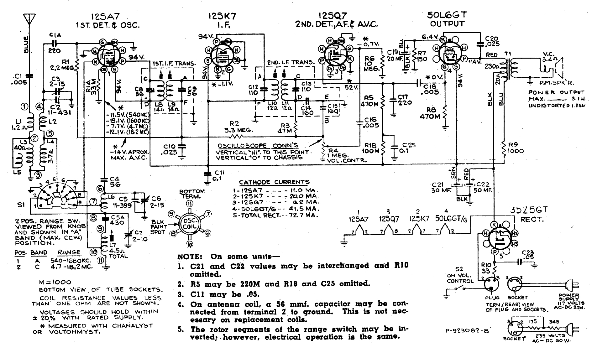
See the schematic below. Fortunately, RCA did see fit to include the value of the trimmer in question, which is C6 in the schematic below (2 to 15 pF).

It had its issues (don't they all). This one was missing its safety interlock and has no back. I resolved the interlock issue by cutting a piece of plastic and creating my own entrance point for the AC cord. I drilled two holes in the plastic and ran the separated zip cord through the holes, tying the wires in an Underwriters' knot inside the chassis.
It's an unbelievably cheap radio. And it is a hot chassis set!
But I digress.
I started aligning the set this evening. All went well until I got to the first SW alignment step - the 18 mc oscillator adjustment. As I turned the trimmer screw, I suddenly realized that there was no resistance. The screw was stripped! More accurately, the screw itself was fine, but the Bakelite panel into which the screw had been threaded was stripped.
Talk about a cheap way to build a variable capacitor...I find it hard to believe that RCA, which built quality stuff before WWII, became so cheap immediately postwar.
So I am in a dilemma.
The only option I can think of is to do away with the movable plate of the original trimmer and install a separate trimmer capacitor to replace it.
But I thought I would ask the opinions of my esteemed colleagues here first before proceeding. (Actually, I won't be doing anything more to it for a few to several weeks.)
What say you?
See the schematic below. Fortunately, RCA did see fit to include the value of the trimmer in question, which is C6 in the schematic below (2 to 15 pF).
--
Ron Ramirez
Ferdinand IN


![[-] [-]](https://philcoradio.com/phorum/images/bootbb/collapse.png)


