08-17-2020, 12:24 AM
The schematic shows a detail of that cap assembly. It is curious as 2 leads are connected to the same terminal. I would suspect that that is a part that is left over from a previous design. But if you follow the schematic and the detail of the capacitor, you will come out good. I recently completed 2 37-116's and looked closely at the connections to the leads from that can. I have pics of the connections. It does work out per the schematic, and does work in the real world.
The three leads per the schematic are white with a black tracer, brown and red. There is no yellow. One of the .1's is connected to the Wht/Blk, the other end of that .1 is connected to ground. The other .1 is connected to Brown with the other end of the .1 connected to ground. One end of the .8 is connected to Brown, the other end is connected to Red. that is different than Nathan's description, so investigate carefully.
I think the red and the white/blk are connected together, with the white /blk and red connected to one of the 490K resistors and the Brown connected to the other 490K resistor.
Is that clear as mud? Look carefully at the Rider schematic as there is a detail of the part 89, 89A and 89B cap.
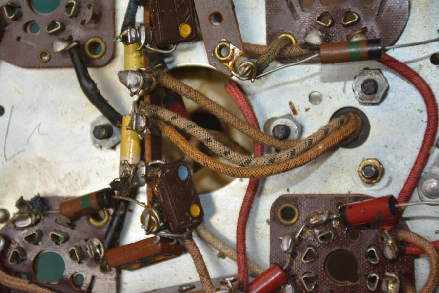
Here is a pic of the leads from the cap can:


![[-] [-]](https://philcoradio.com/phorum/images/bootbb/collapse.png)


