02-12-2021, 02:16 AM
I've begun a "serious" alignment. I've started with the IF. This radio has 4 IF transformers. Selectivity is controlled by varying the center frequency of all of the primary and secondary IF transformers except the primary of the first and the secondary of the forth - stagger tuning accomplished by a single shaft controlling 6 3-plate variable caps. 3 increase capacity and 3 decrease capacity as the selectivity control is turned. The IF is peaked in the most selective position of the control. Then, as the selectivity control is turned, the various stages are detuned to broaden the response curve the IF system. It seems, from my experience here, that it is very difficult to get an even transition from most selective to broadest frequency response. I'm having trouble keeping the response curve fully centered on the IF frequency of 465 kHz. This forces me to retune when I go from very selective to very broad frequency response. I'm thinking there will be compromises!
As the response curve broadens for higher fidelity, the sensitivity naturally goes down so Scott included a variable control on the selectivity that changes the bias voltage on the AGC system to compensate.. It's not perfect, but does a pretty good job of compensating.
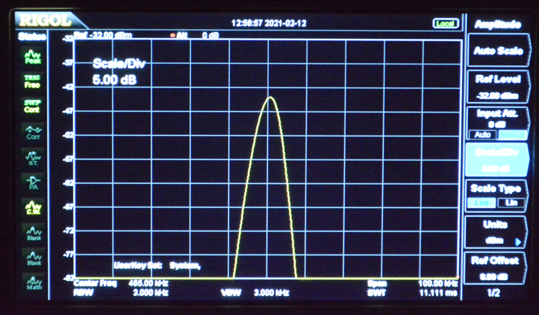
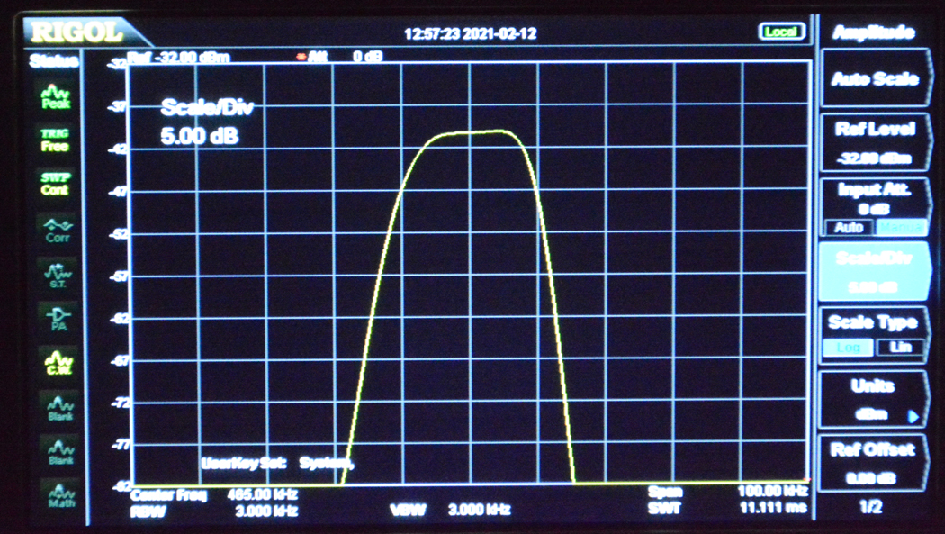
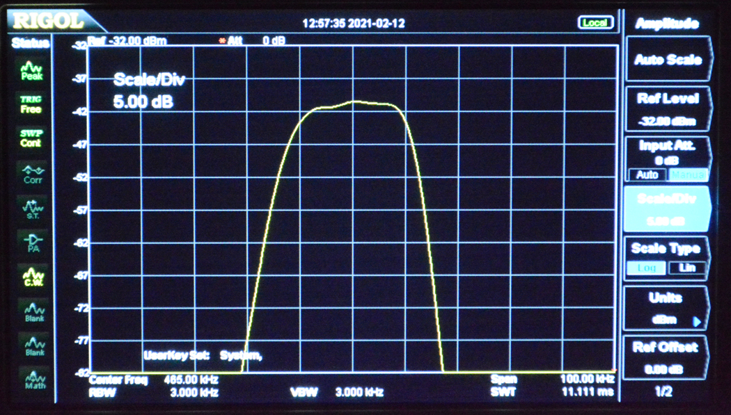
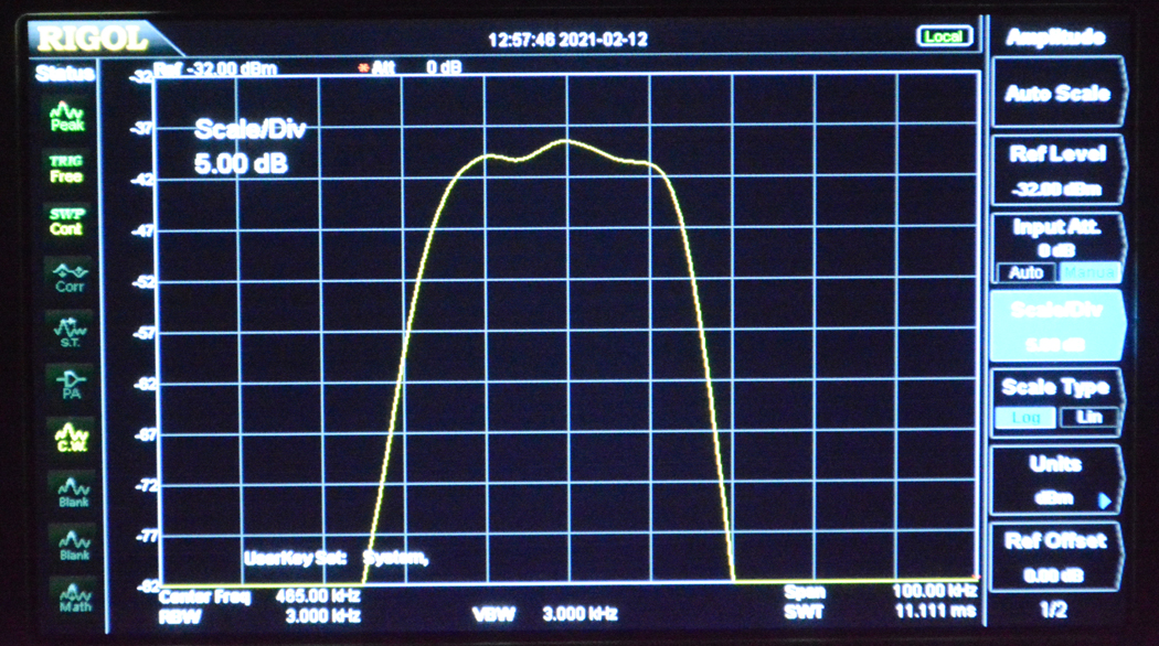
A spectrum analyzer is very useful in this process as I can see every very slight change in the response curve as I change the adjustments. I need to figure out how to keep the center frequency at exactly 465 kHz at all positions of the selectivity control. I may have to tweak the 6 variable caps individually. Could be hours of playing/experimenting. Fun, right!?
Following are a few pics of the Spectrum Analyzer at various positions of the selectivity control from highest selectivity to broadest frequency response. 10 kHz/division horizontal, 5 db/division vertical. You can see the curve broaden out as i turn the control to max fidelity. I just need to make everything more symmetrical. Fun Stuff!!


![[-] [-]](https://philcoradio.com/phorum/images/bootbb/collapse.png)


