09-13-2021, 10:07 PM
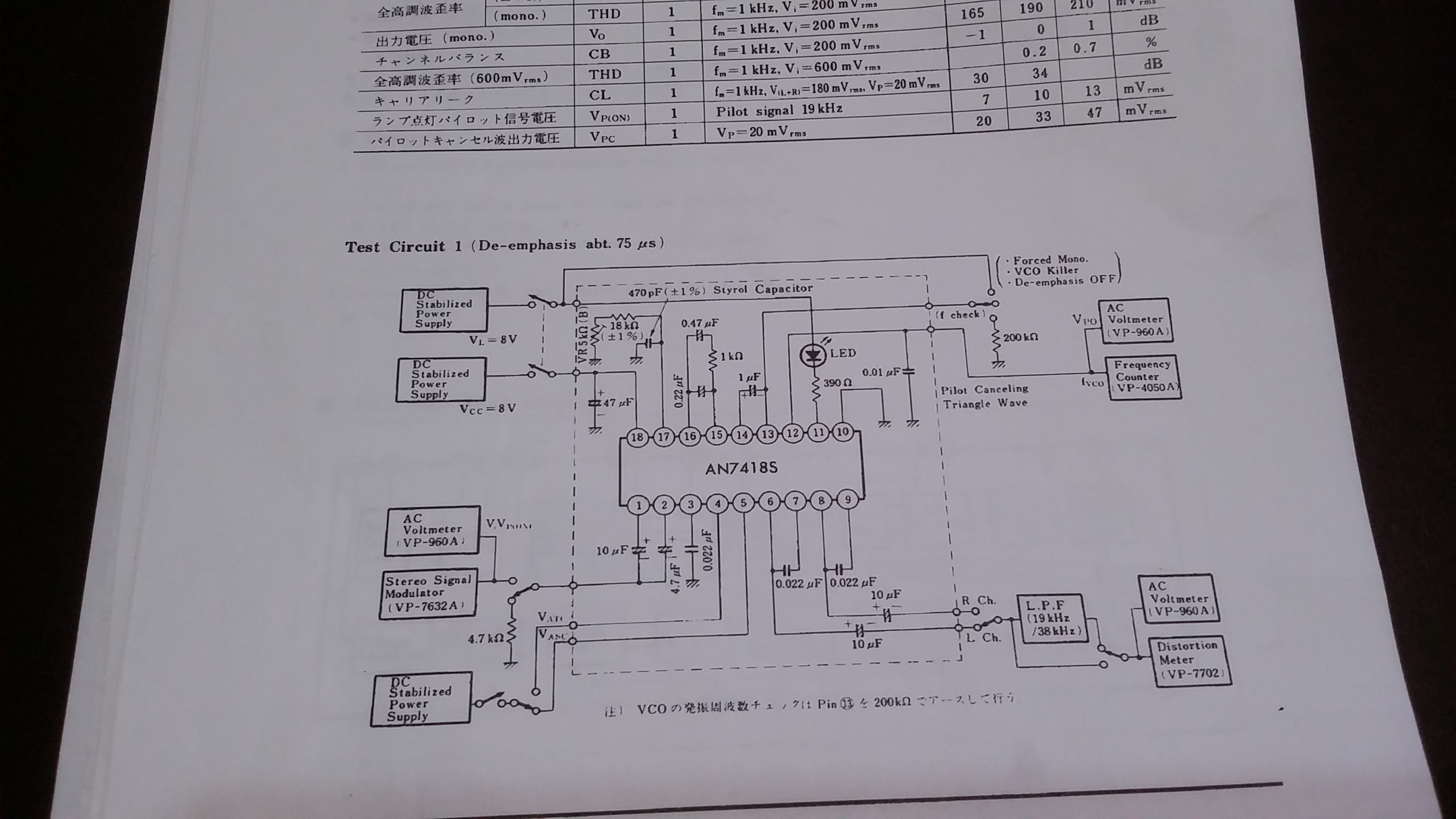
Here's the nitty gritty right here.

For the P.S the 17.5v from the receiver is dropped first by a resistor then thru a 78L08v reg.
The other two transistors are to isolate the 17.5v stereo lamp circuit from blowing out the led driver in the 8v chip.
First is a pnp which is turn on by the led drive which then turns on a npn to pull down the actual lamp ground for the stereo ind.
Only other thing of note is the cap for the vco. It calls for a polystyrene one. I think it's supposed to be more stable than most other types.
The reason I chose this IC chip was ebay for about 13 bucks. They were part of a module board for car stereo. the boxes say panasonic on them.
I am sure there are obsolete by now. There are still some chips by them selves on ebay.
And I do have a magical link to a pdf data sheet I found. It's to somewhere in japan. It took me almost an hour to find it.
And yes it works good. It's always nice when something you build works.
For the P.S the 17.5v from the receiver is dropped first by a resistor then thru a 78L08v reg.
The other two transistors are to isolate the 17.5v stereo lamp circuit from blowing out the led driver in the 8v chip.
First is a pnp which is turn on by the led drive which then turns on a npn to pull down the actual lamp ground for the stereo ind.
Only other thing of note is the cap for the vco. It calls for a polystyrene one. I think it's supposed to be more stable than most other types.
The reason I chose this IC chip was ebay for about 13 bucks. They were part of a module board for car stereo. the boxes say panasonic on them.
I am sure there are obsolete by now. There are still some chips by them selves on ebay.
And I do have a magical link to a pdf data sheet I found. It's to somewhere in japan.
And yes it works good. It's always nice when something you build works.
!!!!!!!!!!!!!!!!!!!RESISTANCE IS FUTILE!!!!!!!!!!!!!!!!!!!!!!
/\/\/\/\/\/\/\/\/\
[Image: http://philcoradio.com/phorum/images/smi...on_eek.gif] Chris


![[-] [-]](https://philcoradio.com/phorum/images/bootbb/collapse.png)


