11-23-2021, 04:26 PM
Hamilton,
"...make sure that 66,64A other two capacitors get mounted with their negative lead mounted to the chassis..."
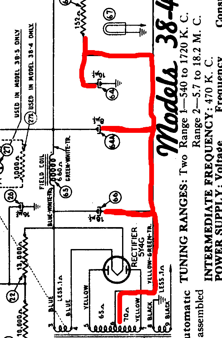
The bottom (negative) legs of caps 66 and 64A should NOT be connected to chassis as instructed earlier. Please view the image I've attached (sorry it is rotated, I couldn't figure out how to save it as a rotated image). I have highlighted in red the net that connects to the negative leads of caps 66, 64A, and 64. Note that this red wire connects to the center tap of the HV secondary of the power transformer (item 68). This point is not the chassis! The HV center tap is the most negative voltage in the radio, and it is different than the chassis (which is usually the B- node, commonly referred to as ground).
The chassis is indicated by the triangular symbol that connects to the positive lead of cap 64.
So at the risk of repeating myself, the negative leads of all three of those electrolytic caps (i.e. 64, 64A, and 66) connect to the HV center tap and not to the chassis.

Good Luck
Jon
"...make sure that 66,64A other two capacitors get mounted with their negative lead mounted to the chassis..."
The bottom (negative) legs of caps 66 and 64A should NOT be connected to chassis as instructed earlier. Please view the image I've attached (sorry it is rotated, I couldn't figure out how to save it as a rotated image). I have highlighted in red the net that connects to the negative leads of caps 66, 64A, and 64. Note that this red wire connects to the center tap of the HV secondary of the power transformer (item 68). This point is not the chassis! The HV center tap is the most negative voltage in the radio, and it is different than the chassis (which is usually the B- node, commonly referred to as ground).
The chassis is indicated by the triangular symbol that connects to the positive lead of cap 64.
So at the risk of repeating myself, the negative leads of all three of those electrolytic caps (i.e. 64, 64A, and 66) connect to the HV center tap and not to the chassis.
Good Luck
Jon


![[-] [-]](https://philcoradio.com/phorum/images/bootbb/collapse.png)


