01-01-2022, 06:46 PM
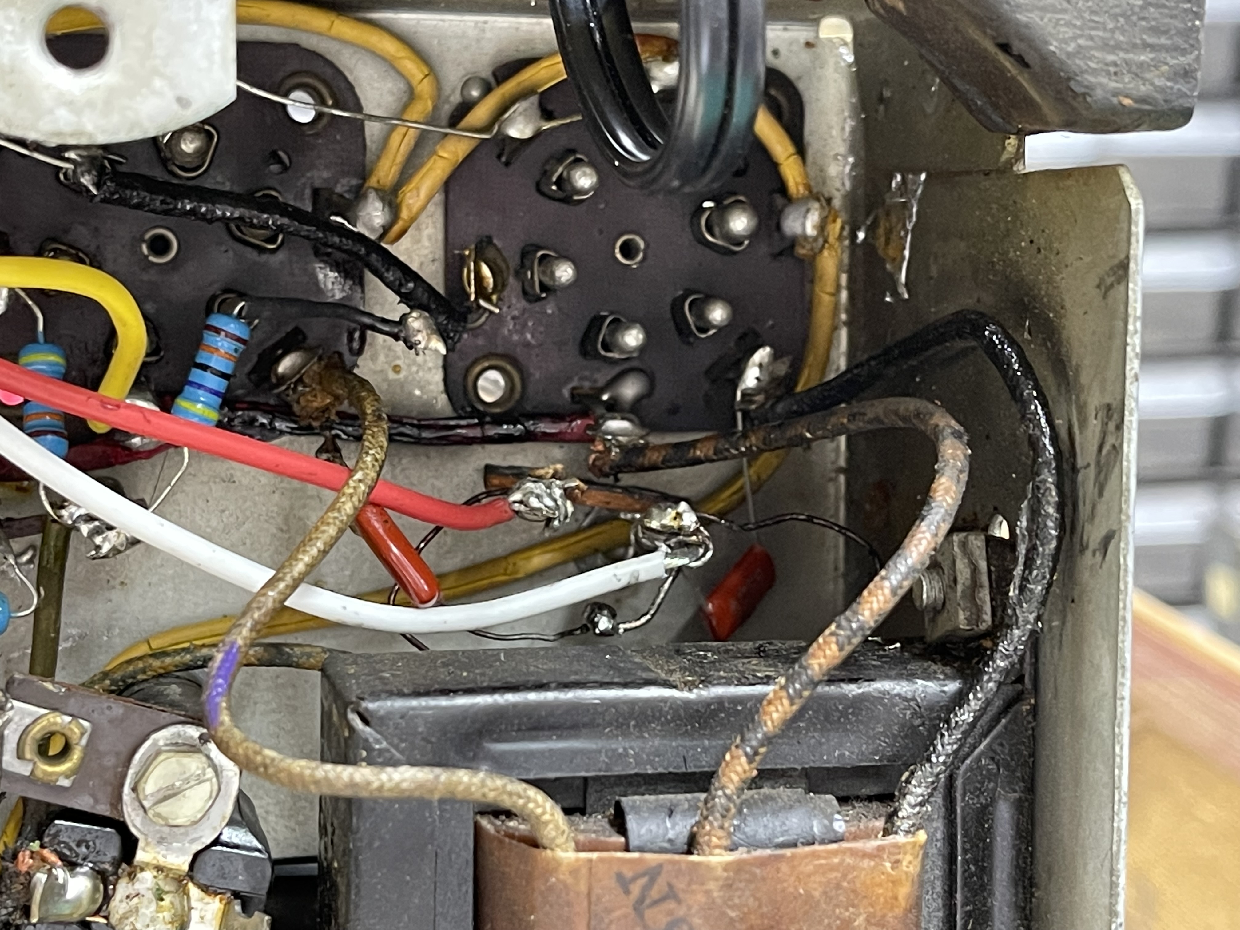
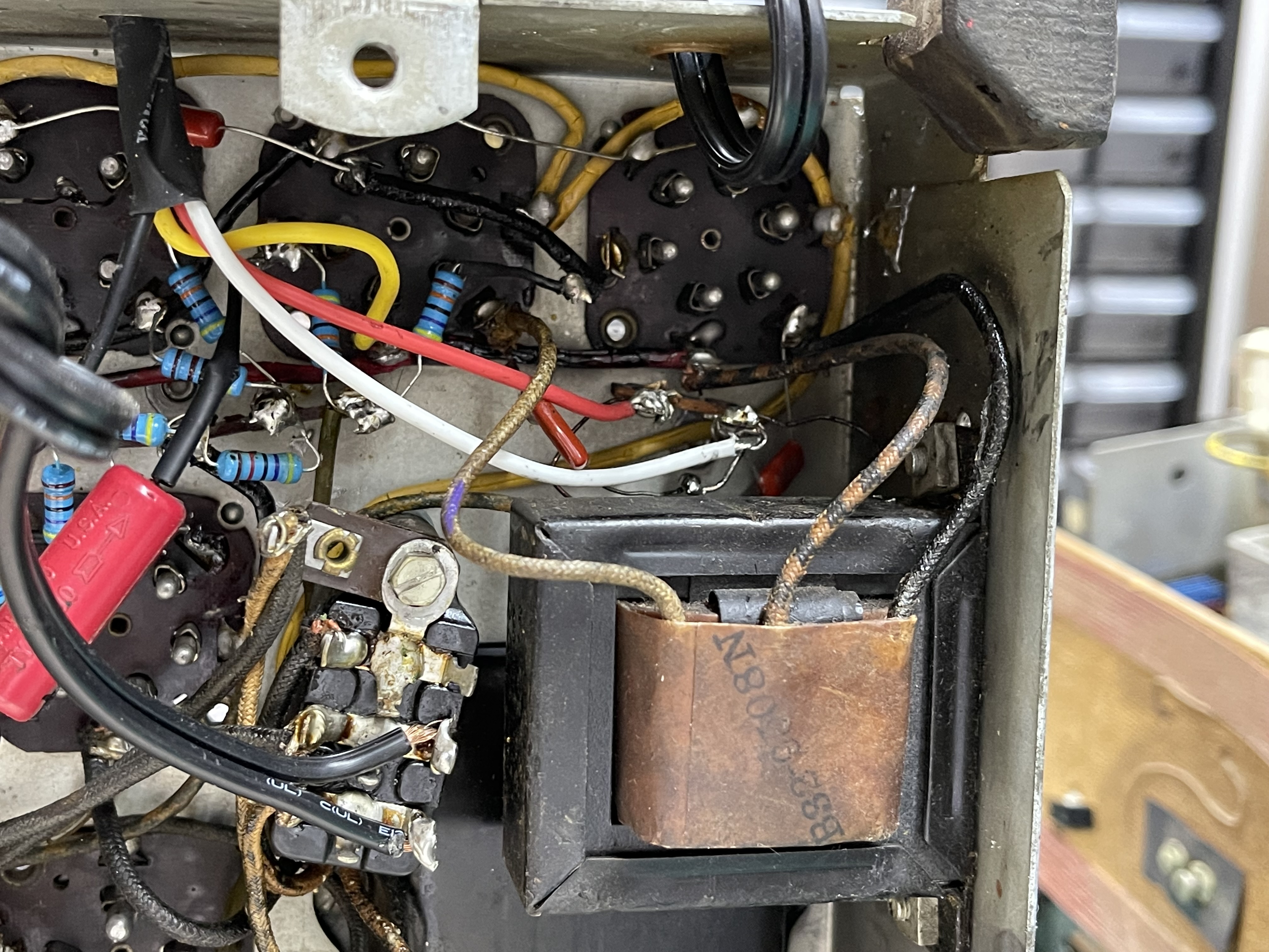
I traced from the OPT (black and white wires) to each Pin #2 x #42 tubes as expected. I am not sure what the #85 capacitor is based on the schematic so I am going to include some pictures that may help.
This is a time when I wished I had a clear picture of before I replaced parts and after! Lesson learned.
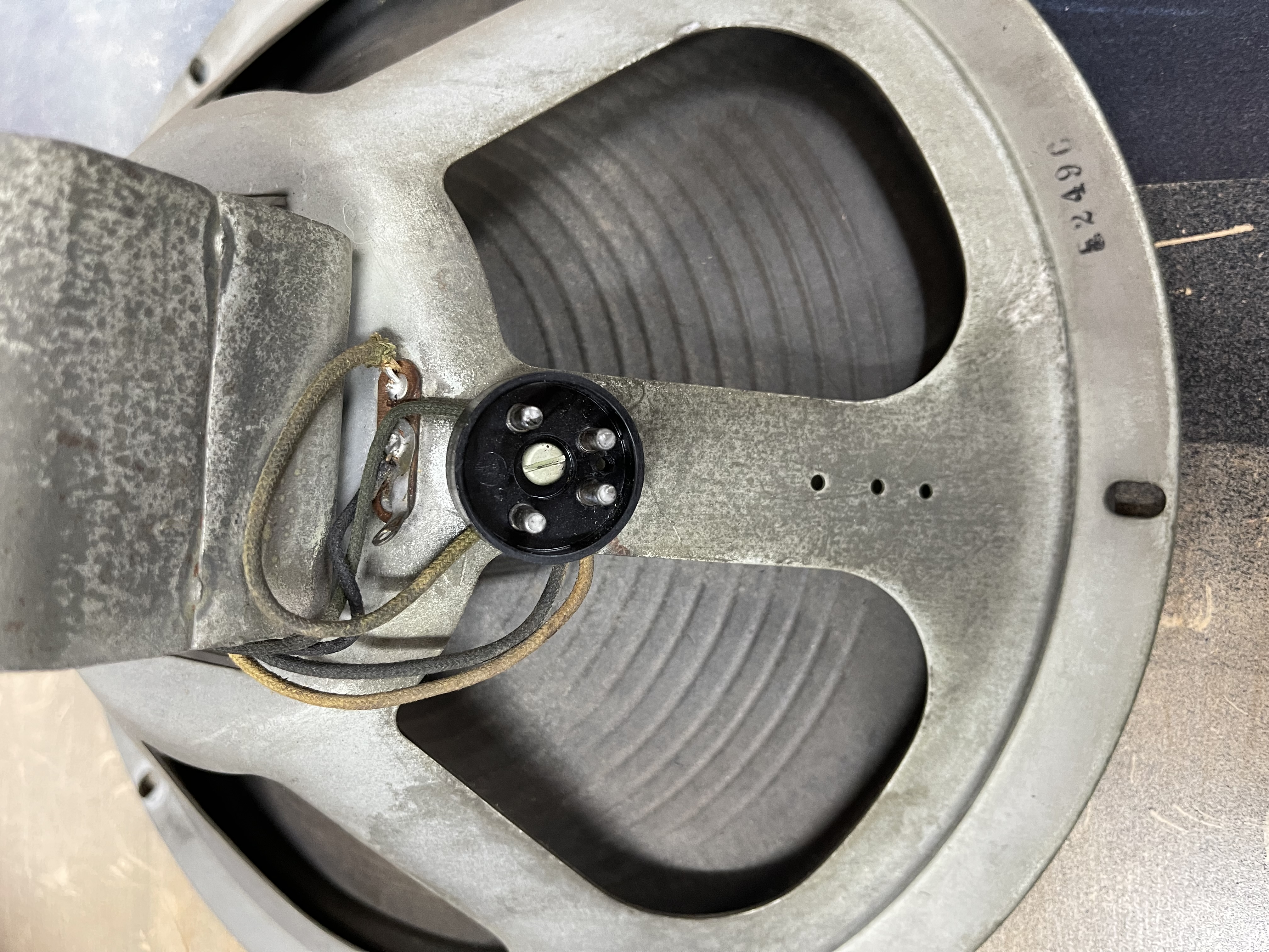
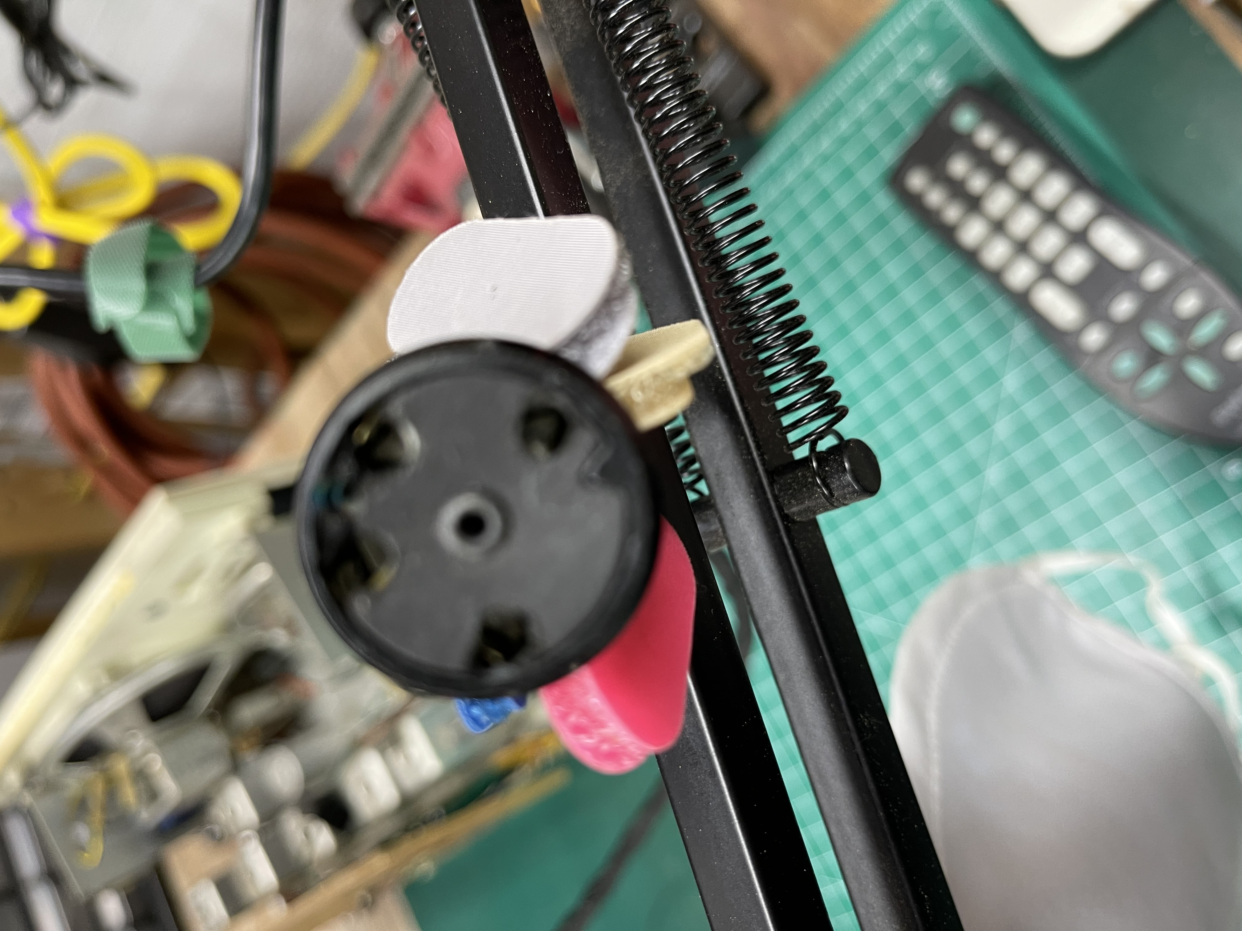
The speaker has a connection as you can see and since they were frayed and cracked, I ran new ones up through the chassis and made connectors on the other side so it would be 'safe'. The yellow, red, black and white wires that are in the shrink wrap are the ones I brought in.
You can see the 2 orange drop capacitors that I used to replace the paper ones. I do have some X2 capacitors I could use if those are the ones that could fail and make the chassis hot.


![[-] [-]](https://philcoradio.com/phorum/images/bootbb/collapse.png)


