03-02-2022, 01:04 PM
Progress ...
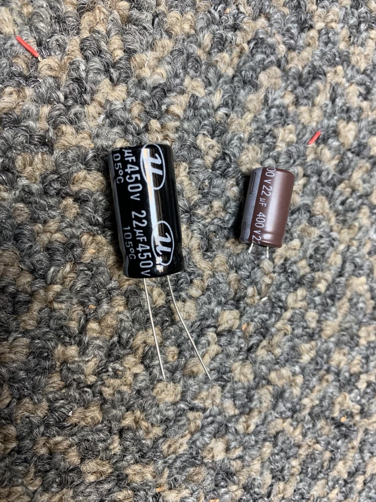
I decided to follow Rons advice to some degree and am upgrading the main filter caps and screen caps with some I had from Mouser. You can see the size difference here on the 22uf 400 vs. 22uf 450v from mouser. The others in the circuit wont have as much voltage or ripple.
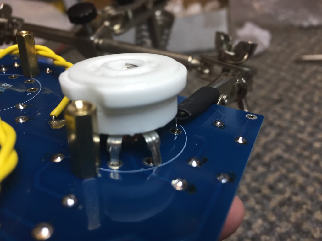
You have to kinda watch the pins on the tube sockets when inserting to the PC board, Seems like they kind of want to escape. I found it was best to install the spacers 1st on the PC, then insert the tube sockets.
The completed PC board. I did not solder the tube sockets at this point. I will wait until the board is mounted and the sockets are level with the chassis before I solder. I detest crooked tubes and sockets.
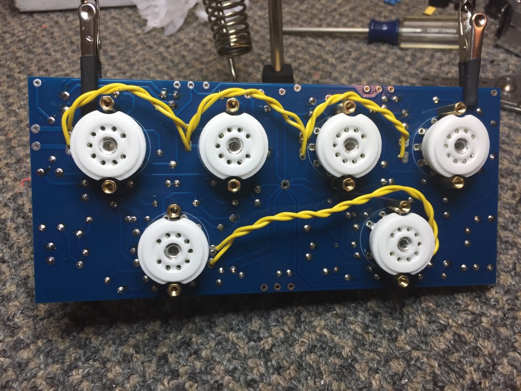
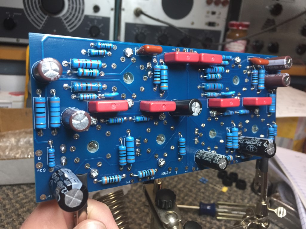
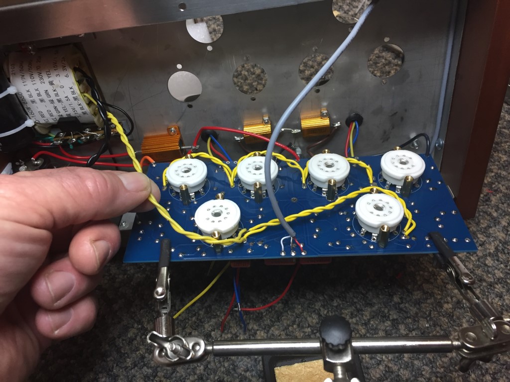
I left plenty of wire so the board can be removed for service if needed without unsoldering. The input cable is shielded and the filament wires will go straight down against the chassis.
*Note that the output tubes and voltage amp tubes are on separate filament windings, also on the voltage amp tubes, you have to solder the filament leads on the PC board on a couple extra pads near the tube sockets. Not a fan of this but it works. The output tubes have clearly labeled pads on the edge of the PC board. You have to jumper the filaments of the output tubes as shown. There are no connecting traces, just extra pads to solder to. Again, not a fan of this, but it works.
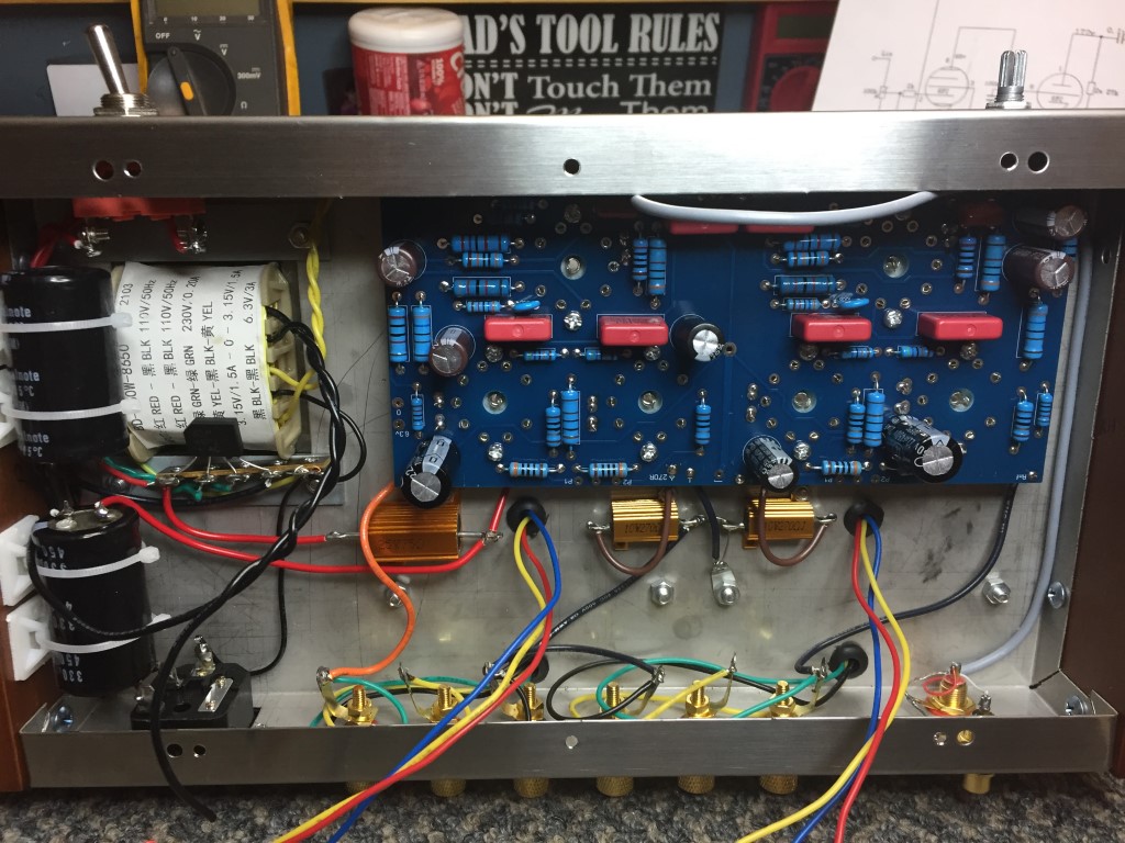
The final installation. I still need to solder the wires for the output xformers and a few other things. This is where I quit for the night.
I decided to follow Rons advice to some degree and am upgrading the main filter caps and screen caps with some I had from Mouser. You can see the size difference here on the 22uf 400 vs. 22uf 450v from mouser. The others in the circuit wont have as much voltage or ripple.
You have to kinda watch the pins on the tube sockets when inserting to the PC board, Seems like they kind of want to escape. I found it was best to install the spacers 1st on the PC, then insert the tube sockets.
The completed PC board. I did not solder the tube sockets at this point. I will wait until the board is mounted and the sockets are level with the chassis before I solder. I detest crooked tubes and sockets.
I left plenty of wire so the board can be removed for service if needed without unsoldering. The input cable is shielded and the filament wires will go straight down against the chassis.
*Note that the output tubes and voltage amp tubes are on separate filament windings, also on the voltage amp tubes, you have to solder the filament leads on the PC board on a couple extra pads near the tube sockets. Not a fan of this but it works. The output tubes have clearly labeled pads on the edge of the PC board. You have to jumper the filaments of the output tubes as shown. There are no connecting traces, just extra pads to solder to. Again, not a fan of this, but it works.
The final installation. I still need to solder the wires for the output xformers and a few other things. This is where I quit for the night.
If I could find the place called "Somewhere", I could find "Anything"
Tim
Jesus cried out and said, "Whoever believes in me , believes not in me but in him who sent me" John 12:44


![[-] [-]](https://philcoradio.com/phorum/images/bootbb/collapse.png)


