03-10-2022, 12:40 PM
Progress from last night:
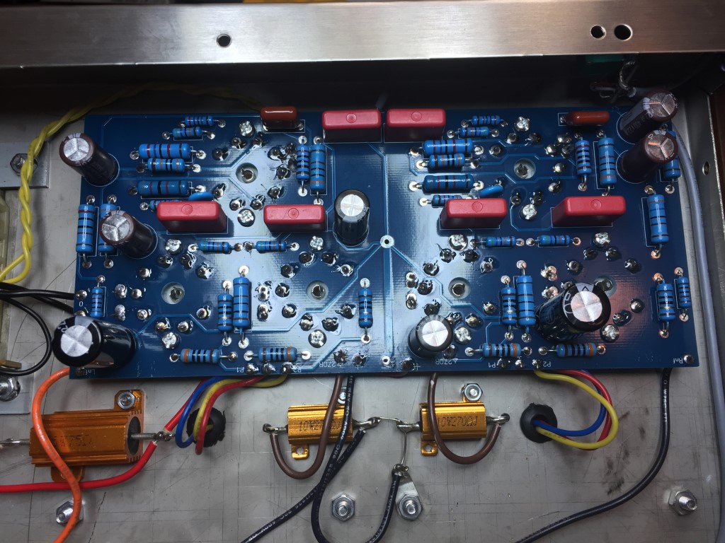
After attaching the PCB (hopefully for the last time), I pushed the tube sockets tight against the chassis, double checked to make sure all pins were in their place, then soldered. I soldered 2x just to make sure it was a good connection. I got the output transformer wires soldered on. I found lightly & carefully tinning the stranded wire helped it go in.

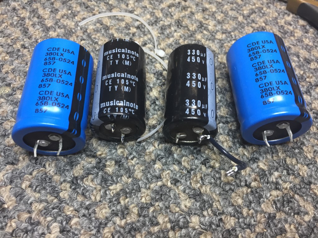
A comparison of the supplied electrolytics vs. the CDE.

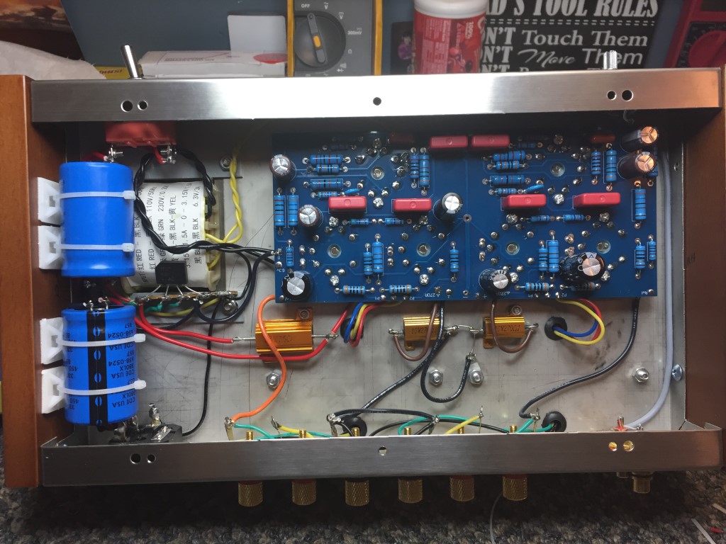
They were a lot bigger and fit was tight, but they are in.

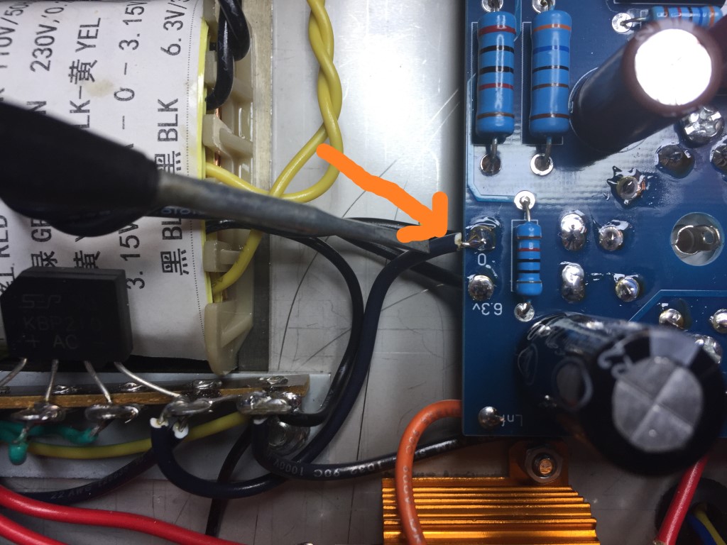
One mistake I made with my last build was not grounding one side of the filament winding. It produced an annoying hum among other things. It's NOT on the schematic, but this shows where I connected the ground for the output tubes. The voltage amp tubes have the filament center tap grounded. The current rating is the same for both filament windings, so I connected it like what appeared in the picture of the completed amp build shown on the auction site. One additional thing I did was to add a ground from the - on the PCB to connect to the ground on the terminal strip, just to insure if there's any resistance on the chassis it has a direct path to the B-

I did a no tube/no load partial power up and things look good so far. I did a few resistance checks 1st from the B+ to ground and didn't see anything unusual. I only powered up to about 60v and voltages looked about right.
After attaching the PCB (hopefully for the last time), I pushed the tube sockets tight against the chassis, double checked to make sure all pins were in their place, then soldered. I soldered 2x just to make sure it was a good connection. I got the output transformer wires soldered on. I found lightly & carefully tinning the stranded wire helped it go in.
A comparison of the supplied electrolytics vs. the CDE.
They were a lot bigger and fit was tight, but they are in.
One mistake I made with my last build was not grounding one side of the filament winding. It produced an annoying hum among other things. It's NOT on the schematic, but this shows where I connected the ground for the output tubes. The voltage amp tubes have the filament center tap grounded. The current rating is the same for both filament windings, so I connected it like what appeared in the picture of the completed amp build shown on the auction site. One additional thing I did was to add a ground from the - on the PCB to connect to the ground on the terminal strip, just to insure if there's any resistance on the chassis it has a direct path to the B-
I did a no tube/no load partial power up and things look good so far. I did a few resistance checks 1st from the B+ to ground and didn't see anything unusual. I only powered up to about 60v and voltages looked about right.
If I could find the place called "Somewhere", I could find "Anything"
Tim
Jesus cried out and said, "Whoever believes in me , believes not in me but in him who sent me" John 12:44


![[-] [-]](https://philcoradio.com/phorum/images/bootbb/collapse.png)


