07-02-2022, 07:06 PM
I have finished rewiring and recapping.
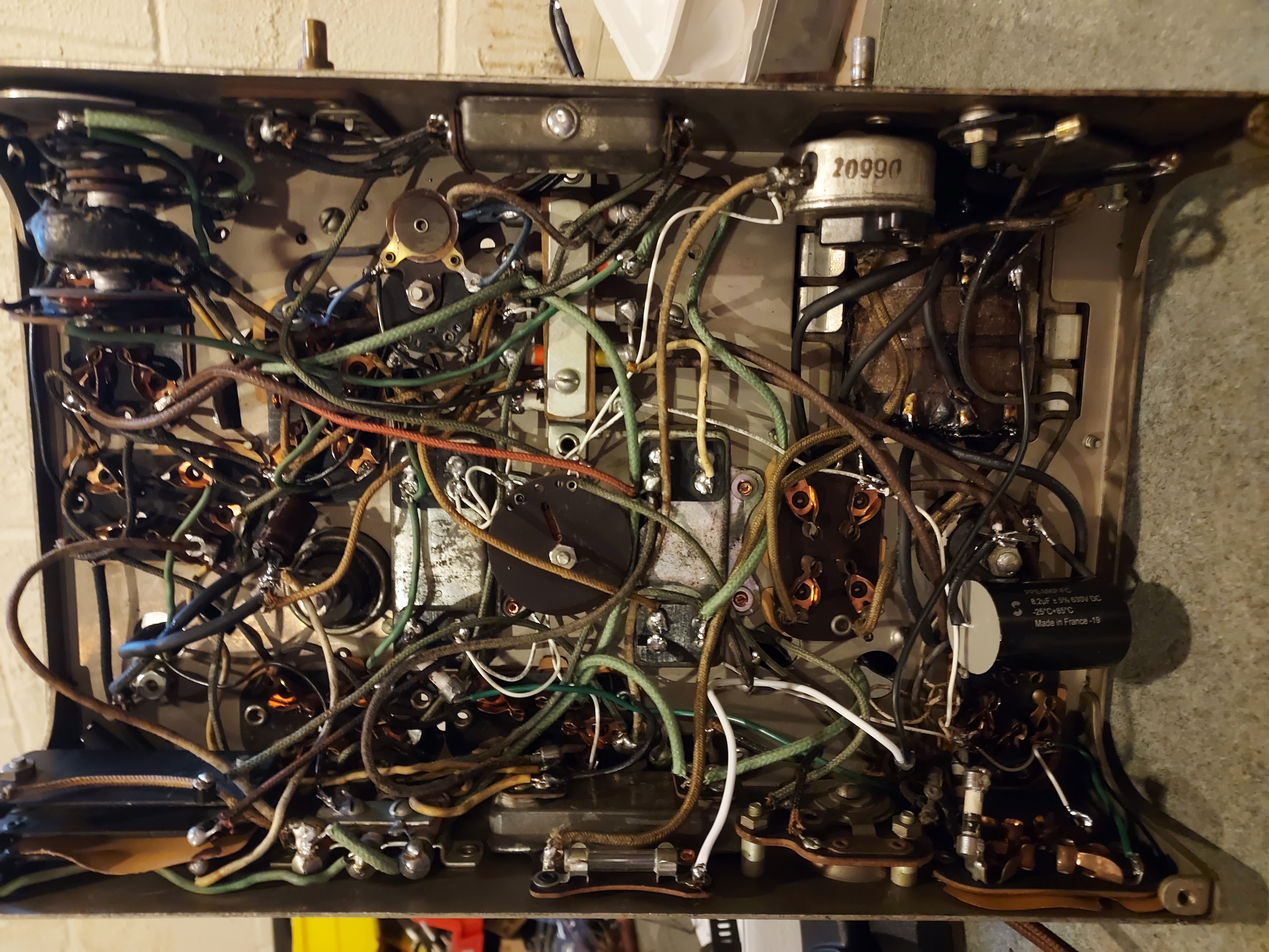
For now I have chosen to not restuff the aluminum electrolytic caps, and used them as holders for the solder posts, to which I attached a good 10uF cap as the second filter, and the Solen 8.2uF (correct value) film cap as the firstd one.
I attached the cord and checked the transformer; it seems to produce correct values (5V for the rectifier tube filament and 950V between plates) at 110V AC.
I bought 3mm an 5mm headshring adhesive tubing to encase the wires that went to the transformer (they are cloth-covered thinner type that has an extra insulation that has crumbled) and used it; it is thick-walled type and makes the insulation look right; across the chassis, I also used some to encase the wires I was not willing to desolder, like the tar-potted ones inside the RF coils (AK loves that stuff).
Most resistors I checked are OK, despite being the "Early Philco"-type dogbones (those used in 20 and 70). I have left it be.
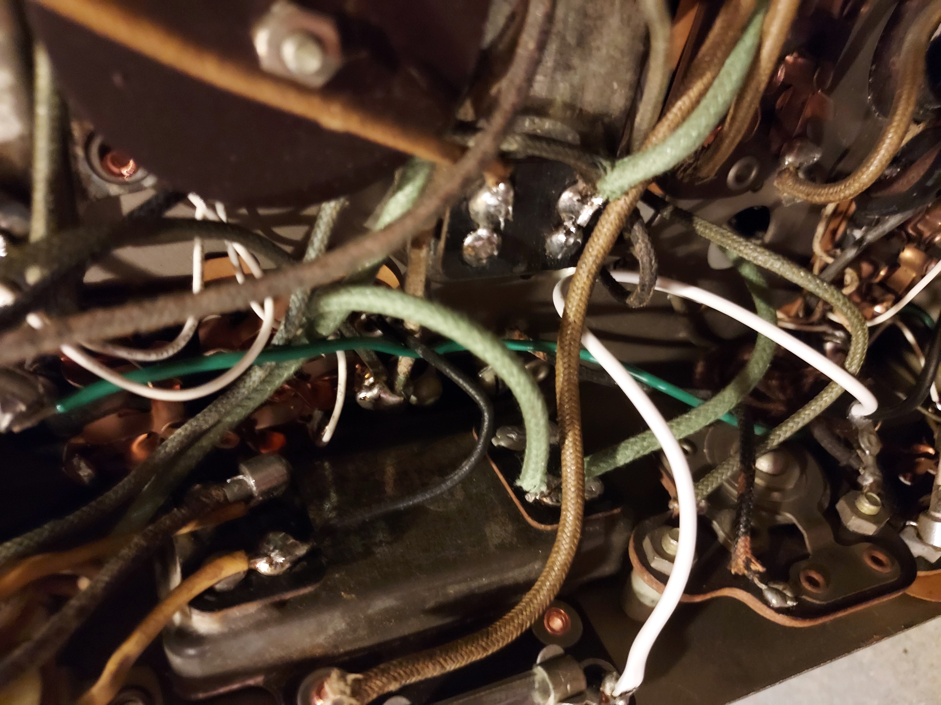
This is how those wires look
The remnant of the thick insulation can be seen.


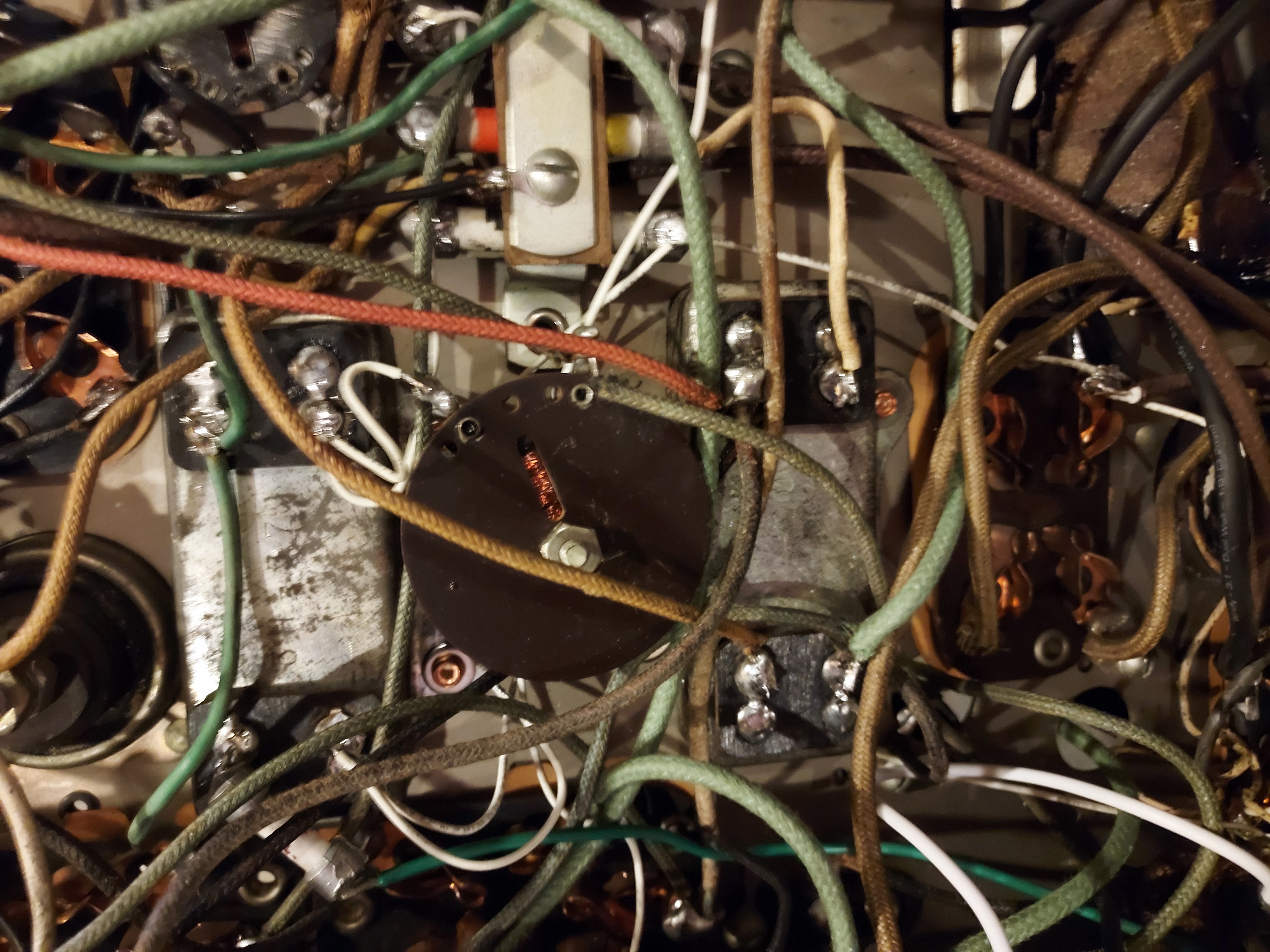
And after the heatshrink tubing put over. It can also be seen how I used the solder post and the electrolytic cap as the holder for it, to attach the replacement cap for the electrolytic.

The chassis and the cap cans are here


For now I have chosen to not restuff the aluminum electrolytic caps, and used them as holders for the solder posts, to which I attached a good 10uF cap as the second filter, and the Solen 8.2uF (correct value) film cap as the firstd one.
I attached the cord and checked the transformer; it seems to produce correct values (5V for the rectifier tube filament and 950V between plates) at 110V AC.
I bought 3mm an 5mm headshring adhesive tubing to encase the wires that went to the transformer (they are cloth-covered thinner type that has an extra insulation that has crumbled) and used it; it is thick-walled type and makes the insulation look right; across the chassis, I also used some to encase the wires I was not willing to desolder, like the tar-potted ones inside the RF coils (AK loves that stuff).
Most resistors I checked are OK, despite being the "Early Philco"-type dogbones (those used in 20 and 70). I have left it be.
This is how those wires look
The remnant of the thick insulation can be seen.
And after the heatshrink tubing put over. It can also be seen how I used the solder post and the electrolytic cap as the holder for it, to attach the replacement cap for the electrolytic.
The chassis and the cap cans are here
People who do not drink, do not smoke, do not eat red meat will one day feel really stupid lying there and dying from nothing.


![[-] [-]](https://philcoradio.com/phorum/images/bootbb/collapse.png)


