08-06-2022, 02:19 PM
Thanks David;
Well I took it apart. There is a coated wire circle clip that comes off first, but I find pushing it out requires the heat gun, and a pair of eagle beaks.
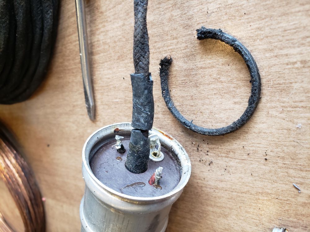
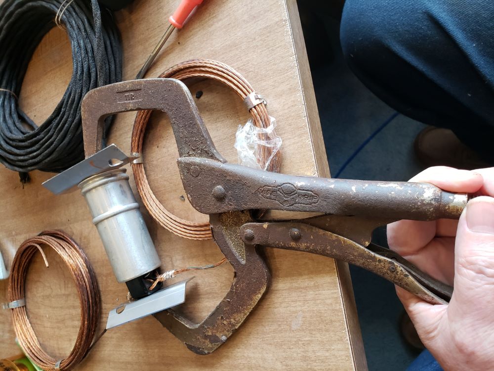
I tried unraveling the soldered antenna leg connections, but wanted to get this done before Christmas, so I snipped them off.
The legs can be reattached, loosing about 4" from each side.
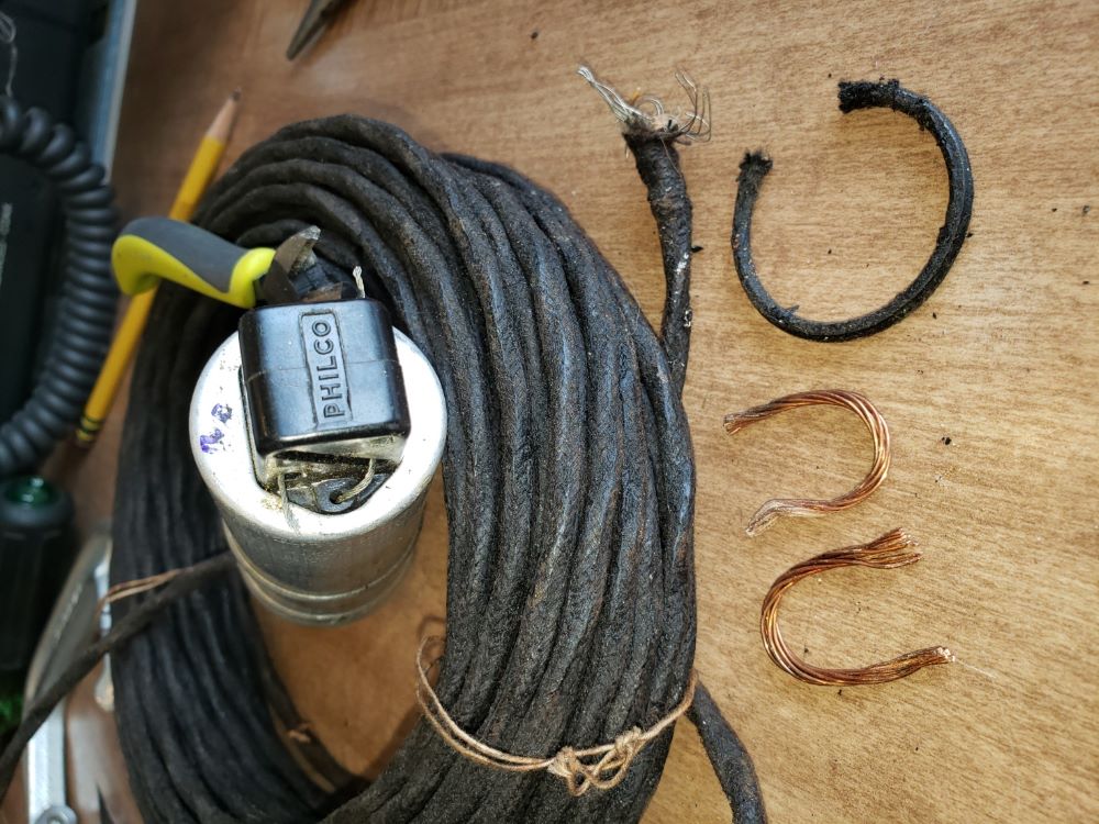
Surprise Surprise! There's tar under that paper!
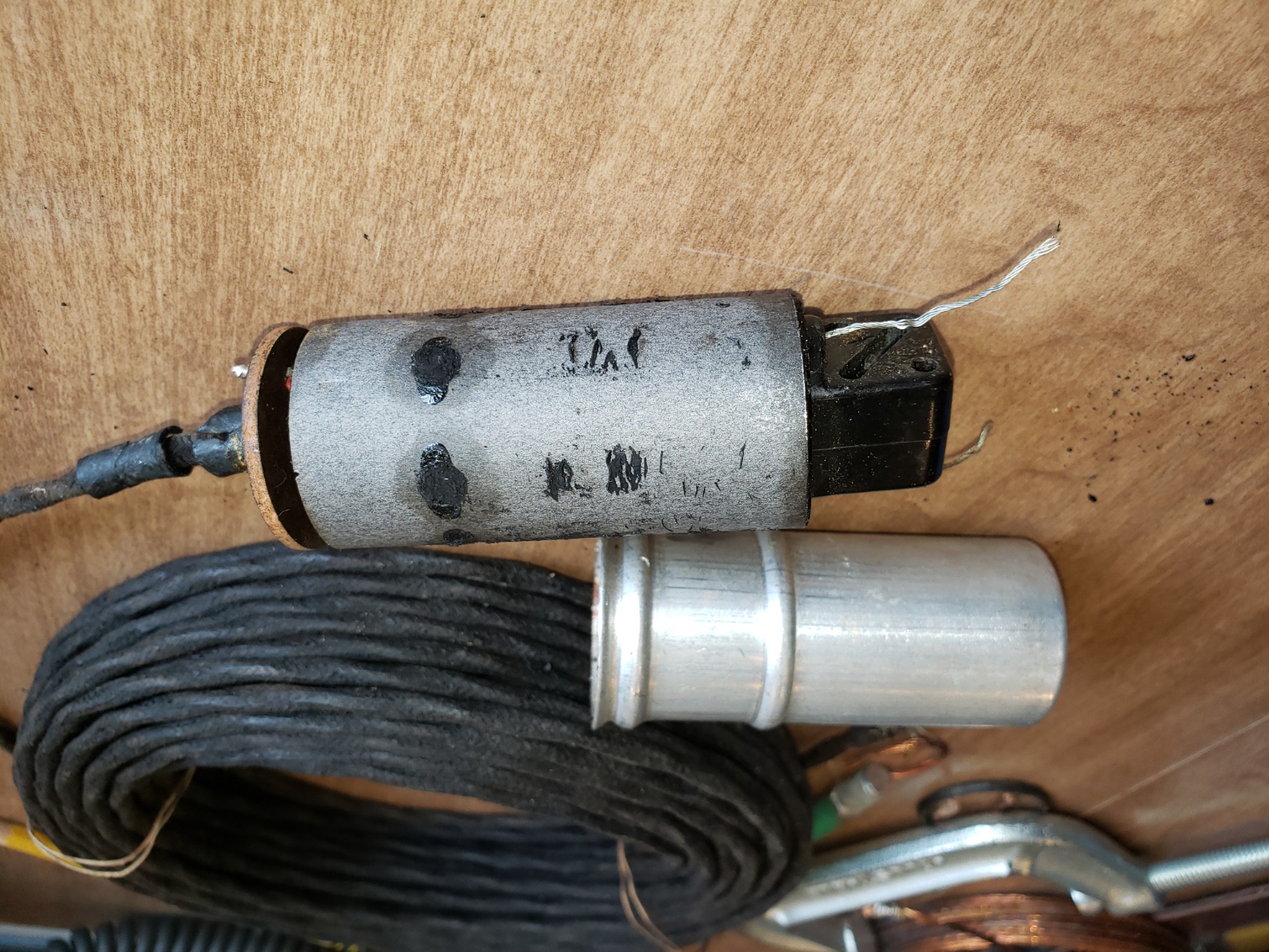
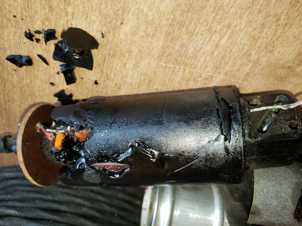
Chipping away, we find 1 resister and 5 capacitors surrounding what might be 2 coils wrapped on the same form
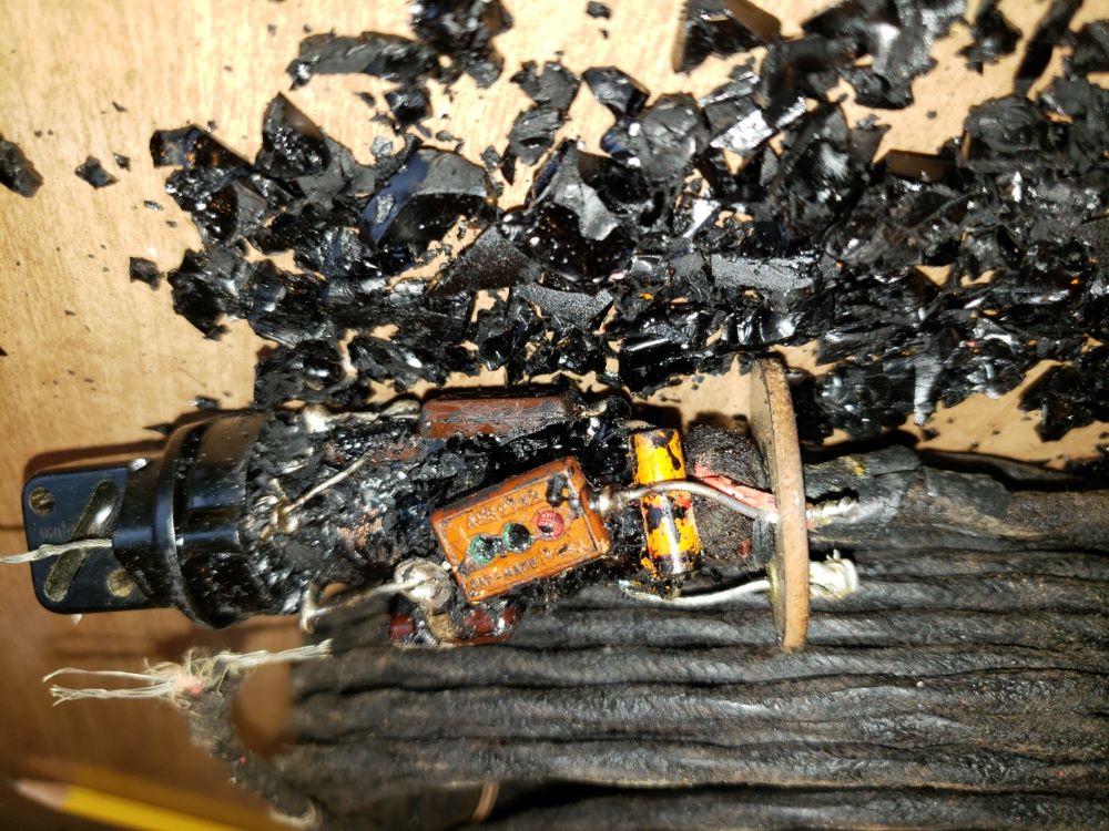
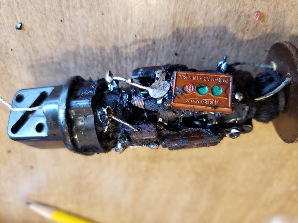
I would like to, at this time thank the OP RGK20m3 for getting me into this mess, see now what you have done!
Now that the legs (ant wires) are removed, I check with the ohm meter Red 1 to Leg 1, and I get 15Meg ohm sinking to about 5Meg ohm which means the capacitors are charging. This holds true for Red 1 to Leg 2, Black 1 to Leg 1, and Black 1 to Leg 2.
And now I realize that I made a mistake on my diagram, the reference to either Leg should have been Meg ohms, not "ohms". I need a digital multi-meter with large font! Can I go back and fix that?
Next up: mapping out the circuit
Well I took it apart. There is a coated wire circle clip that comes off first, but I find pushing it out requires the heat gun, and a pair of eagle beaks.
I tried unraveling the soldered antenna leg connections, but wanted to get this done before Christmas, so I snipped them off.
The legs can be reattached, loosing about 4" from each side.
Surprise Surprise! There's tar under that paper!
Chipping away, we find 1 resister and 5 capacitors surrounding what might be 2 coils wrapped on the same form
I would like to, at this time thank the OP RGK20m3 for getting me into this mess, see now what you have done!
Now that the legs (ant wires) are removed, I check with the ohm meter Red 1 to Leg 1, and I get 15Meg ohm sinking to about 5Meg ohm which means the capacitors are charging. This holds true for Red 1 to Leg 2, Black 1 to Leg 1, and Black 1 to Leg 2.
And now I realize that I made a mistake on my diagram, the reference to either Leg should have been Meg ohms, not "ohms". I need a digital multi-meter with large font! Can I go back and fix that?
Next up: mapping out the circuit


![[-] [-]](https://philcoradio.com/phorum/images/bootbb/collapse.png)


