02-05-2023, 06:15 PM
I concur with all the operational procedures recommend and add.
Use a ten turn link to get the RF signal into the radio do not directly connect to any tuning circuit.
Modulate at 30% and keep the level low. If the upper part of the band is dead move the align frequency by 50khz in the weak direction.
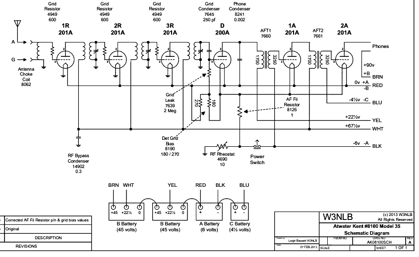
Do keep the "A" supply at the radio at 6 to 6.6 volts. starving the radio will create a bias error. The rheostats provide an initial bias so result is 5 volts on filaments.
Reduced "A" will also paralyze the tubes over long term operation by not completing the thorium cycle, filaments not get hot enough so thorium is stripped and not renewed from the core of the filament wire.
Grid leak detectors must not be overloaded with an RF signal, so excessive signal from either the generator or the antenna must be avoided nor can they deal with 100% modulation without noticeable distortion.
Try: Reducing the RF grid squegging resistors, go as low as 200 ohms or until the stage "takes off" from self oscillation, then increase in 100 ohm steps. They do not have to be equal. Changing this resistor value is a recommendation for TRF's as found in A.H. Ghirardis Radio Troubleshooters Handbook.
https://en.wikipedia.org/wiki/Squegging
Get the radio working properly before experimenting with mods...

It has occurred to me that using a computer P.S. for "A" power not only is too low but the 5 volt return is both grounded to the case of the P.S. and to the "U" power line. That poses a problem if an external ground is used and could compromise the RF rheostat and the AF fixed resistor. As for the fixed resistor it is hidden in a length of varnished cambric as a strand of resistance wire. Can be overlooked as a length of rotted wire and inadvertently replaced with copper...
The common "A" source was a 90 ah L/A battery. This provided a low impedance and bulk of current drop occurs at the rheostats and not in any lightweight wire used for the "A" supply, generally 14 ga from the low impedance source.
Further, the grid return for the detector is via the junction of two bias resistors that are across the "A" supply, again, reduced "A" will effect the bias of the detector. Be sure the detector grid capacitor is not leaking and at the value given.
YMMV
Chas
Use a ten turn link to get the RF signal into the radio do not directly connect to any tuning circuit.
Modulate at 30% and keep the level low. If the upper part of the band is dead move the align frequency by 50khz in the weak direction.
Do keep the "A" supply at the radio at 6 to 6.6 volts. starving the radio will create a bias error. The rheostats provide an initial bias so result is 5 volts on filaments.
Reduced "A" will also paralyze the tubes over long term operation by not completing the thorium cycle, filaments not get hot enough so thorium is stripped and not renewed from the core of the filament wire.
Grid leak detectors must not be overloaded with an RF signal, so excessive signal from either the generator or the antenna must be avoided nor can they deal with 100% modulation without noticeable distortion.
Try: Reducing the RF grid squegging resistors, go as low as 200 ohms or until the stage "takes off" from self oscillation, then increase in 100 ohm steps. They do not have to be equal. Changing this resistor value is a recommendation for TRF's as found in A.H. Ghirardis Radio Troubleshooters Handbook.
https://en.wikipedia.org/wiki/Squegging
Get the radio working properly before experimenting with mods...
It has occurred to me that using a computer P.S. for "A" power not only is too low but the 5 volt return is both grounded to the case of the P.S. and to the "U" power line. That poses a problem if an external ground is used and could compromise the RF rheostat and the AF fixed resistor. As for the fixed resistor it is hidden in a length of varnished cambric as a strand of resistance wire. Can be overlooked as a length of rotted wire and inadvertently replaced with copper...
The common "A" source was a 90 ah L/A battery. This provided a low impedance and bulk of current drop occurs at the rheostats and not in any lightweight wire used for the "A" supply, generally 14 ga from the low impedance source.
Further, the grid return for the detector is via the junction of two bias resistors that are across the "A" supply, again, reduced "A" will effect the bias of the detector. Be sure the detector grid capacitor is not leaking and at the value given.
YMMV
Chas
Pliny the younger
“nihil novum nihil varium nihil quod non semel spectasse sufficiat”


![[-] [-]](https://philcoradio.com/phorum/images/bootbb/collapse.png)


