03-04-2023, 11:23 AM
Hi David,
More info on the wiring for your original speaker and how 3 wires are used for 2 circuits.
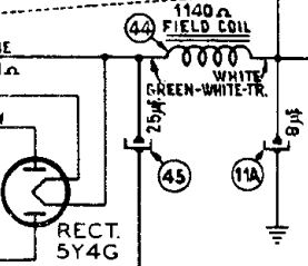
As stated in previous posts, the field coil doesn't have a power supply per se, but it is in series with the "B+" supply. The field coil serves as a choke in the filter system of the B+ Power Supply. The more current drawn by radio circuits, the more power is delivered by the magnet.
There are 3 wires going to the speaker: green / white, white and green. Looking carefully at the plug that is part of the speaker assembly, you will see that the white wire pin has 2 wires coming out of the same pin. one wire goes to the output transformer primary. The other white wire goes to the field coil. The white wire is the output of the field coil, back to the chassis. (See below).
The green /white wire is the "input" from the rectifier cathode and C45.
The white wire is main B+ output going to the audio output transformer, but also back to the chassis and C11A where it is further distributed to the rest of the radio B+ requirements.
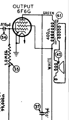
The green wire on the speaker plug is the conductor between the output transformer and the output tube plate.
The secondary of the output transformer connects to the speaker's voice coil. You will see however, that there is another coil in series with the speaker voice coil. This is called the "hum bucking coil" and is used on electrodynamic speakers (speakers that have a field coil electromagnet instead of a permanent magnet field). This is shown in the second attachment, showing the Audio Output stage.
Attached below are 2 shots of the schematic where I hoped to filter out all of the mumbo jumbo and make this clearer. These shots show the field coil connections and the Audio Output transformer connections. Hopefully this helps:
"Do Justly, love Mercy and walk humbly with your God"- Micah 6:8
"Let us begin to do good"- St. Francis
Best Regards,
MrFixr55


![[-] [-]](https://philcoradio.com/phorum/images/bootbb/collapse.png)


