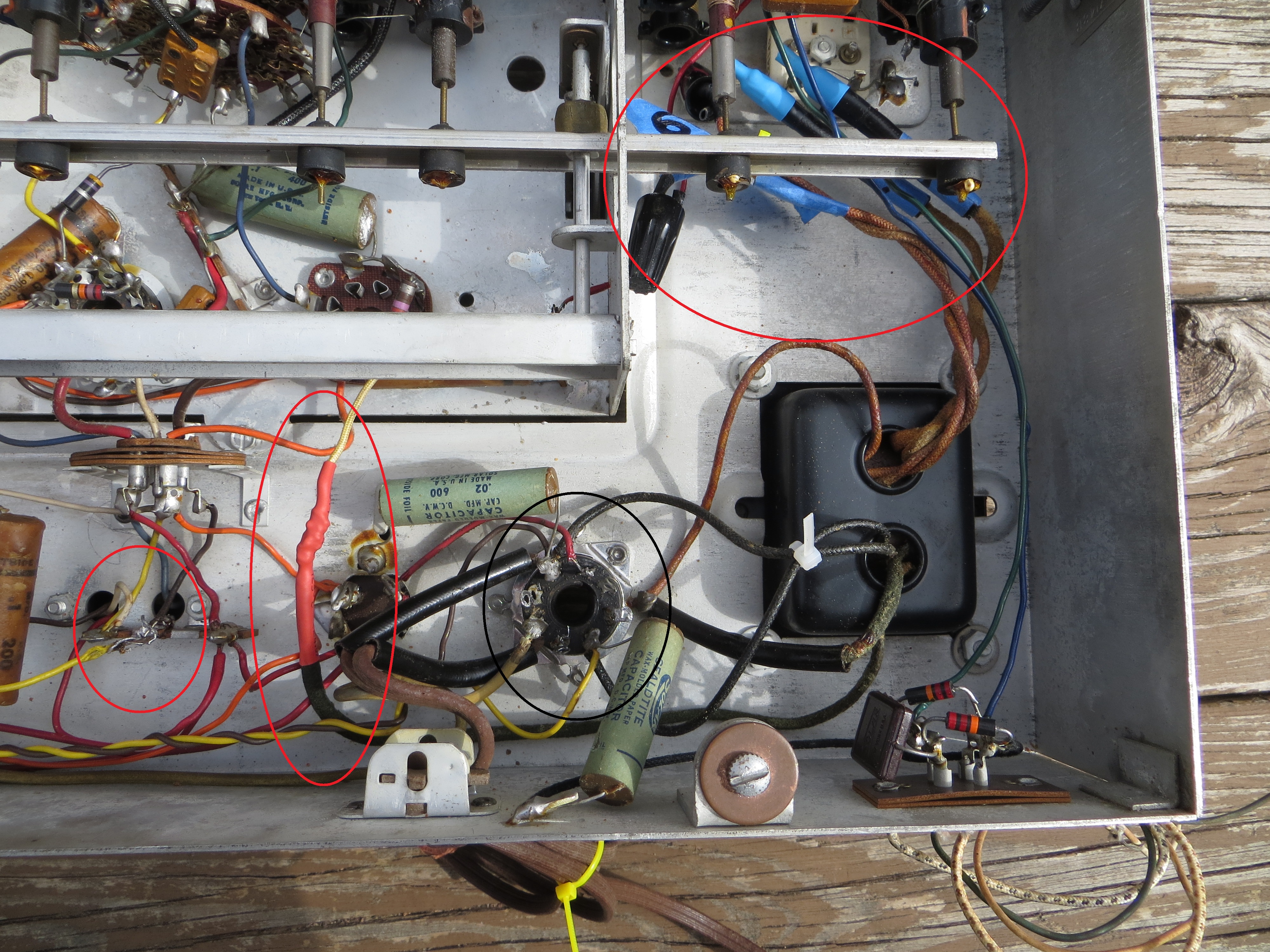
Well, I finally got back to the radio chassis. In an effort to help me understand this beast and minimize my potential harm, I did the following:
1. I know the Rectifier Tube is bad and I still need to replace caps before I can do anything too major.
2. I decided to take the "death voltage" out of the equation by unsoldering the High Voltage and 5 VAC from the Rectifier socket and label/cap them for another day.
3. I decided to eliminate the 6.3 VAC "filament" activity by unsoldering that wire from the terminal block.
4. I then unsoldered the Pilot Light line and shrink wrap it to the 6.3 VAC line.
So, while I don't have a "radio" at this point, I still have "all the parts in the box" and (after replacing the bulbs) the dial lights come on via the Volume Switch. I guess I also technically have power to the phono too.
I did observe the 110 VAC between the two rectifier terminals (as expected) and 110 VAC differential between one terminal and the chassis (GND) due to the CAP-to-GRN. And once the switch was turned ON (releasing power into the transformer), the chassis differential dropped to 55 VAC due to a second CAP-to-GRN now in the circuit. Is that assumption correct and am I still within a "zone of safety"?
See attached photo with circled "mods".


![[-] [-]](https://philcoradio.com/phorum/images/bootbb/collapse.png)


