04-21-2023, 12:14 PM
Not sure it's practical with the typical consumer radio... but does anyone attempt to "improve" on the chassis wiring with neater wire routing and cabling?
Or do you stick to the original rat's nest for authenticity?
Related comment for other beginners like me: The schematic does NOT necessarily correspond to the actual wiring! It may be electrically identical, but it doesn't depict the actual wiring connections.
A common example: Those Philco Bakelite capacitor blocks are often a single 2-lead cap... but the block has eight tie points! So the unconnected middle set may just be a convenient tie point for a wire on the way to somewhere else, while you may be scratching your head wondering why THAT wire connects to THIS cap... it doesn't.
Another example: You'd think the 4-pin jack to the speaker assembly would be shown somehow on the schematic... not on mine. One needs to suss out where the connections are.
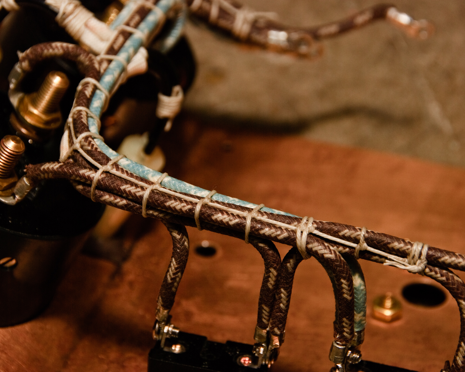
Ah, cable lacing:

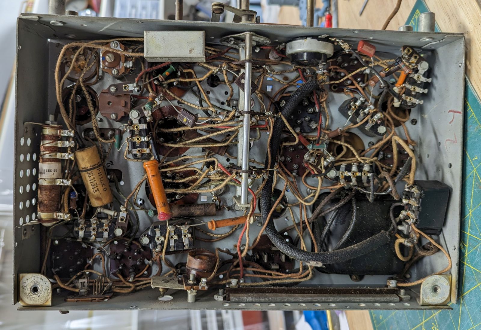
A rat's nest:

Or do you stick to the original rat's nest for authenticity?
Related comment for other beginners like me: The schematic does NOT necessarily correspond to the actual wiring! It may be electrically identical, but it doesn't depict the actual wiring connections.
A common example: Those Philco Bakelite capacitor blocks are often a single 2-lead cap... but the block has eight tie points! So the unconnected middle set may just be a convenient tie point for a wire on the way to somewhere else, while you may be scratching your head wondering why THAT wire connects to THIS cap... it doesn't.
Another example: You'd think the 4-pin jack to the speaker assembly would be shown somehow on the schematic... not on mine. One needs to suss out where the connections are.
Ah, cable lacing:
A rat's nest:


![[-] [-]](https://philcoradio.com/phorum/images/bootbb/collapse.png)


