04-26-2023, 12:14 PM
OK, a question about the filament wiring.
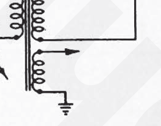
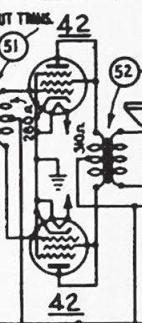
The 655 schematic has the typical format, with filament transformer winding grounded on one side, and an arrow off to the filaments. It also shows most of the cathodes connected to one filament pin AND ground.
I've traced all my wiring (I think), and see:
- NO grounding of the filament circuit anywhere,
- NO connections of cathodes to filament circuit.
Is there any deeper understanding to be had for this situation? I suppose it doesn't matter that the filaments are on their own floating circuit, but why show it differently in the schematic?
EDIT: I'm clearly missing something in my wire tracing, and yet further puzzlement: With all tubes pulled, BOTH sides of the filament circuit measure ZERO ohms to chassis.
How does THAT work?
655 schematic, at transformer:

655 schematic, typical tubes with cathode-filament-ground connections shown:

Actual layout in chassis- No filament grounds, No connection to cathodes:

The 655 schematic has the typical format, with filament transformer winding grounded on one side, and an arrow off to the filaments. It also shows most of the cathodes connected to one filament pin AND ground.
I've traced all my wiring (I think), and see:
- NO grounding of the filament circuit anywhere,
- NO connections of cathodes to filament circuit.
Is there any deeper understanding to be had for this situation? I suppose it doesn't matter that the filaments are on their own floating circuit, but why show it differently in the schematic?
EDIT: I'm clearly missing something in my wire tracing, and yet further puzzlement: With all tubes pulled, BOTH sides of the filament circuit measure ZERO ohms to chassis.
How does THAT work?
655 schematic, at transformer:
655 schematic, typical tubes with cathode-filament-ground connections shown:
Actual layout in chassis- No filament grounds, No connection to cathodes:


![[-] [-]](https://philcoradio.com/phorum/images/bootbb/collapse.png)


