06-11-2023, 01:59 PM
Not too successful.
I changed the sch as follows:
1. The 700 Ohm resistor in series with filaments is replaced with 3.3uF cap.
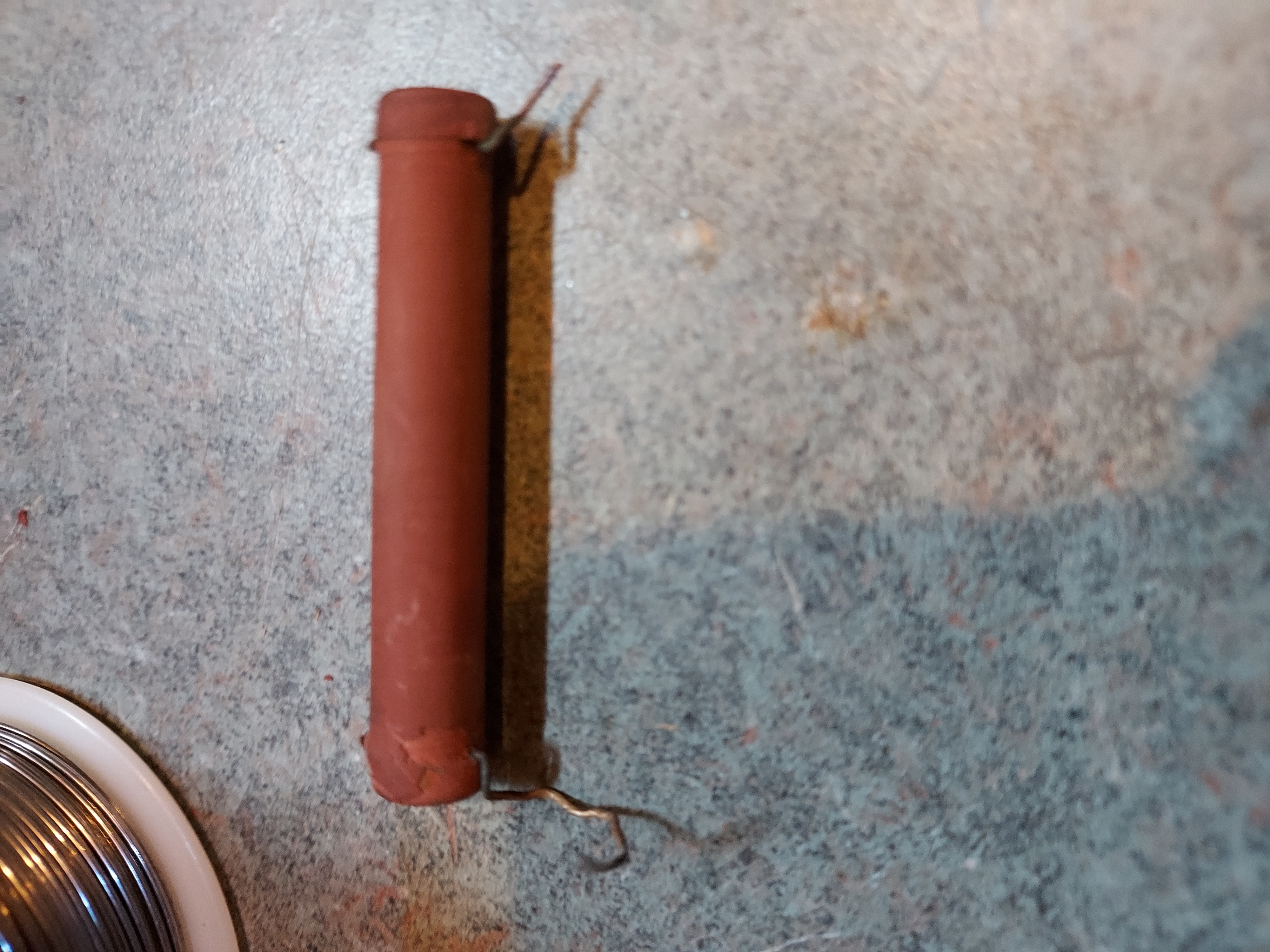
2. The filament of the rectifier is simply shorted. (the short is clearly see in the next photo in the paragraph 3)
3. The rectifier bridge AC IN is connected between the AC lines with the 20 Ohms resistor being replaced by a 60 Ohm NTC thermistor (inrush control needed due to no warm up time). The thermistor is that black disk thingy.
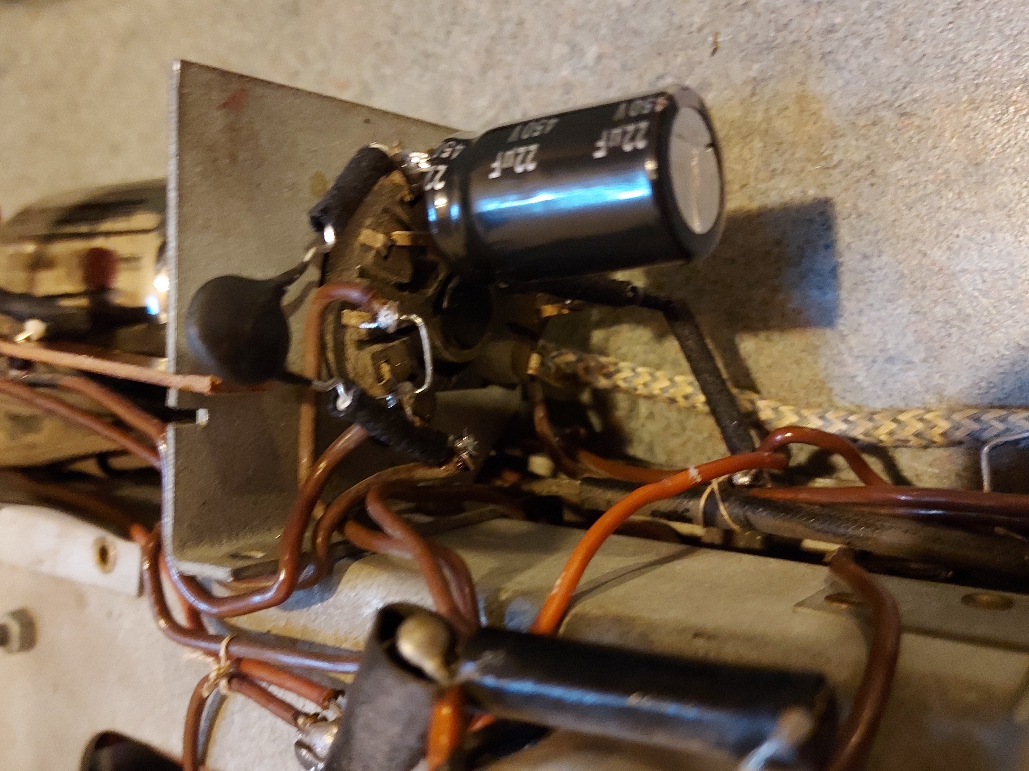
4. The bridge DC OUT is connected between the Rect tube Cathode (1st filter cap Positive) and the 1st filter cap Negative.
5. The filament string side that went to the fused AC line (the Negative of the rectifier) is disconnected and together goes to the Bridge AC IN (one of the bridge's inputs already mentioned in #3).
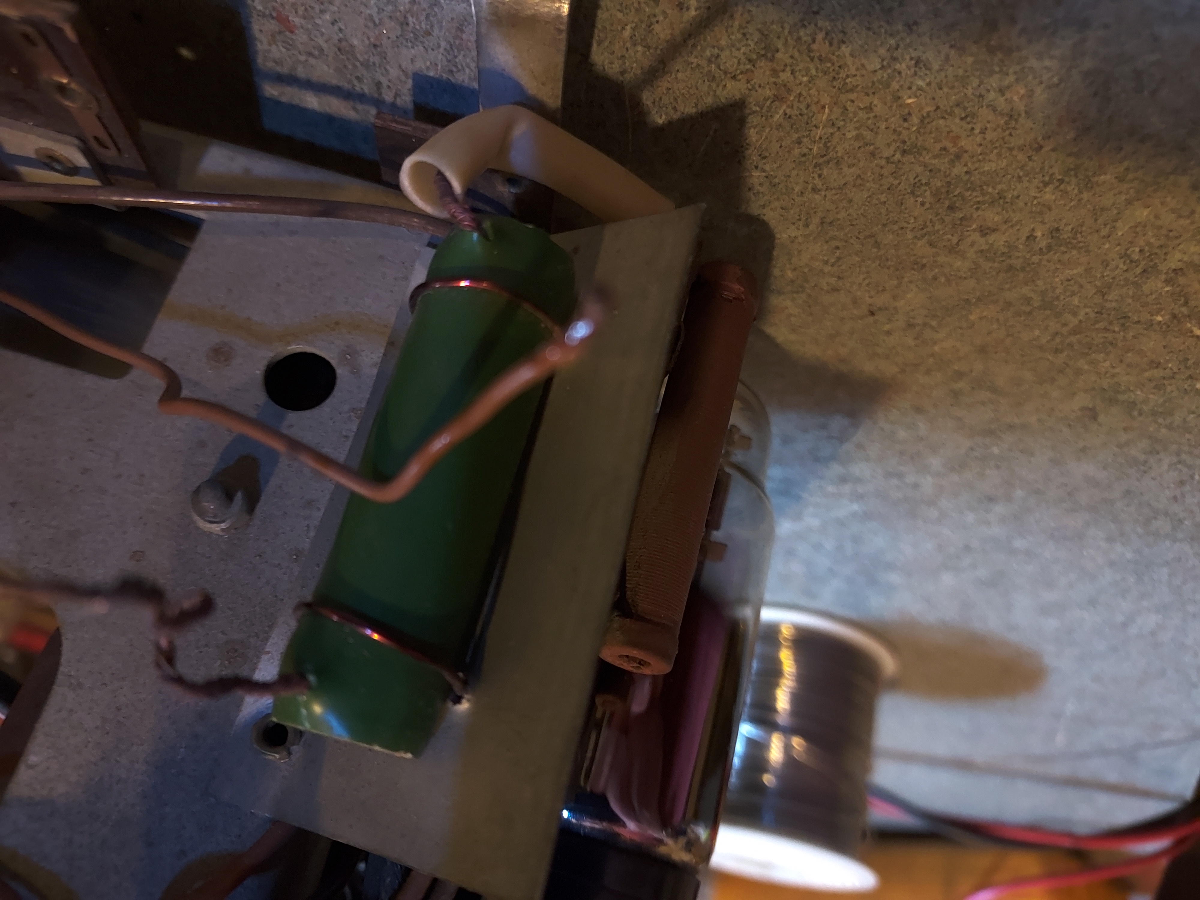
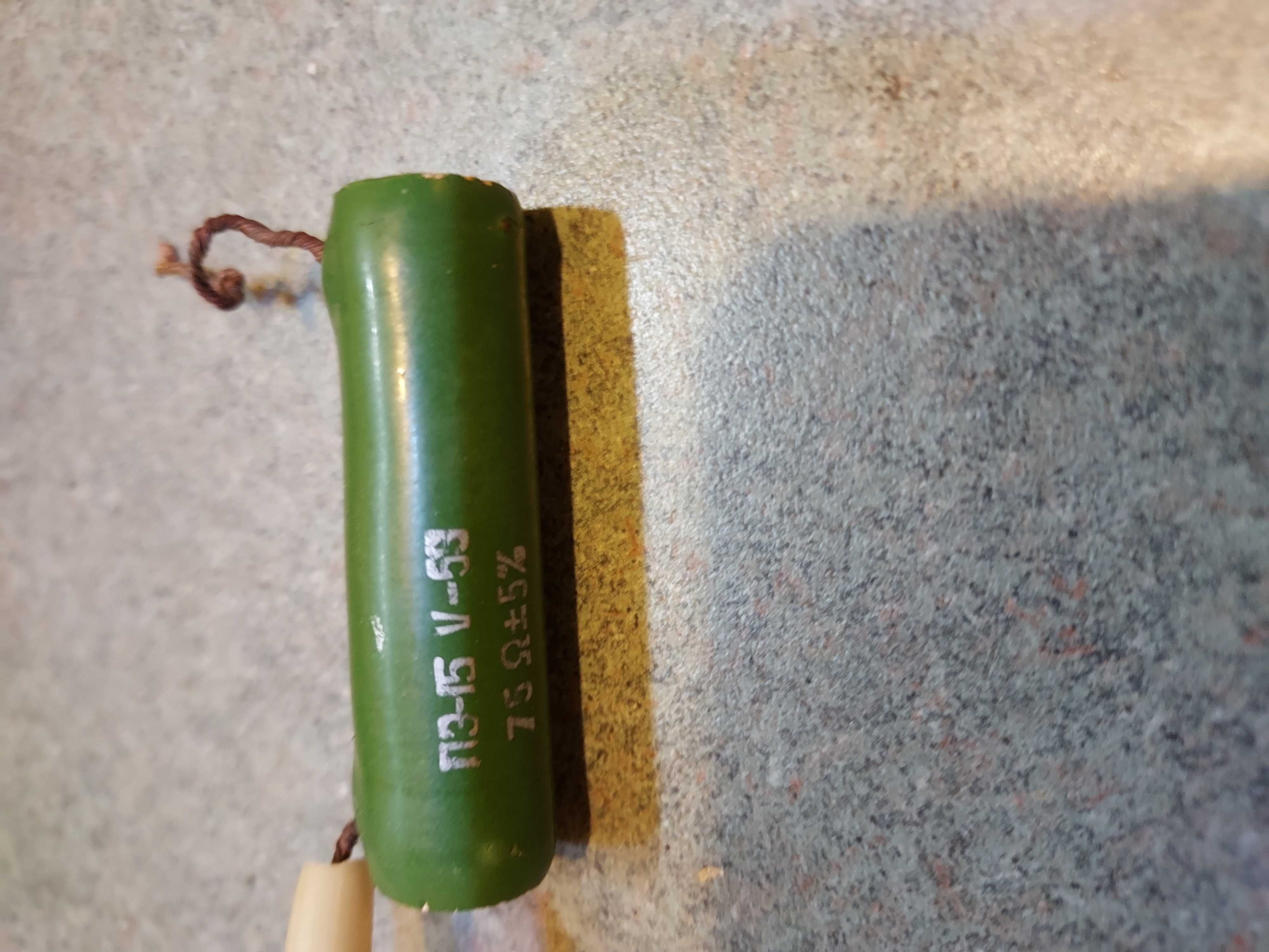
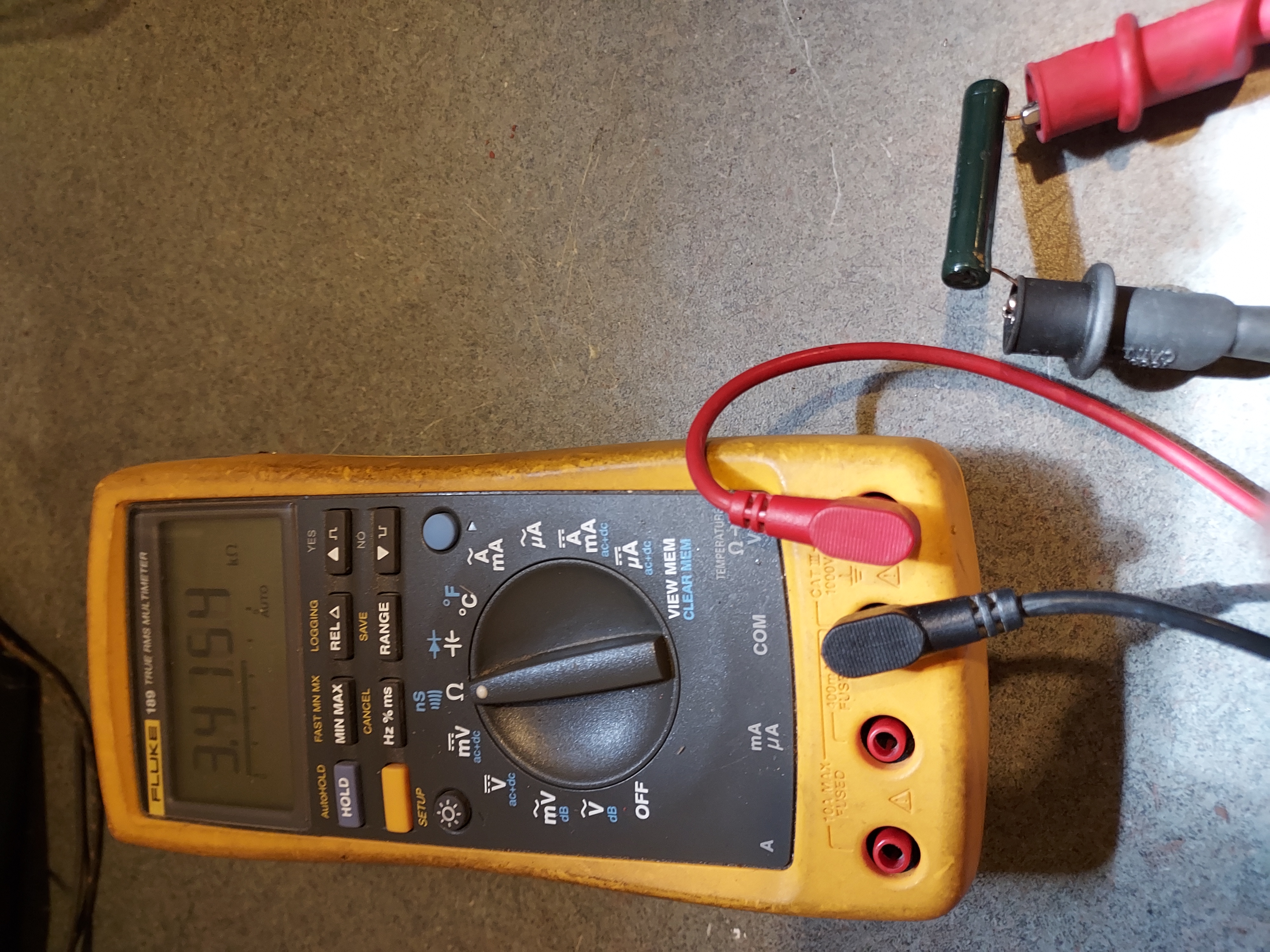
6. A green Soviet-made large wire-wound resistor, of 70 Ohm, for whatever reason added in front of both 700 ohm and 20 Ohm (perhaps due to poor power control in that part of the former USSR, where it is known to go to 250VAC) was removed.
Also the 2K filter resistor was 3.3K, so it was replaced.
The result is, the radio playes but is very hummy.
Also the DC 220V at the rectifier output was about 145V. So the full bridge diode rectifier does not compensate for the lower input AC by much larger margin than I was hoping for (I was hoping the Half-bridge lowers the voltage but the DC level was 225V DC with the 220V AC in. 165VDC to 120VAC is much better ratio but still not enough).
So I increased the input filter cap to 330uF (vs 16uF). The DC rose to 165V DC. But hum, though smaller, is still very pronounced. I wonder if this is due to the fact that the filaments were connected to the Negative before, and now they are not. I might try inserting a small cap between the fused input and the Negative, but I doubt it will help much.
I changed the sch as follows:
1. The 700 Ohm resistor in series with filaments is replaced with 3.3uF cap.
2. The filament of the rectifier is simply shorted. (the short is clearly see in the next photo in the paragraph 3)
3. The rectifier bridge AC IN is connected between the AC lines with the 20 Ohms resistor being replaced by a 60 Ohm NTC thermistor (inrush control needed due to no warm up time). The thermistor is that black disk thingy.
4. The bridge DC OUT is connected between the Rect tube Cathode (1st filter cap Positive) and the 1st filter cap Negative.
5. The filament string side that went to the fused AC line (the Negative of the rectifier) is disconnected and together goes to the Bridge AC IN (one of the bridge's inputs already mentioned in #3).
6. A green Soviet-made large wire-wound resistor, of 70 Ohm, for whatever reason added in front of both 700 ohm and 20 Ohm (perhaps due to poor power control in that part of the former USSR, where it is known to go to 250VAC) was removed.
Also the 2K filter resistor was 3.3K, so it was replaced.
The result is, the radio playes but is very hummy.
Also the DC 220V at the rectifier output was about 145V. So the full bridge diode rectifier does not compensate for the lower input AC by much larger margin than I was hoping for (I was hoping the Half-bridge lowers the voltage but the DC level was 225V DC with the 220V AC in. 165VDC to 120VAC is much better ratio but still not enough).
So I increased the input filter cap to 330uF (vs 16uF). The DC rose to 165V DC. But hum, though smaller, is still very pronounced. I wonder if this is due to the fact that the filaments were connected to the Negative before, and now they are not. I might try inserting a small cap between the fused input and the Negative, but I doubt it will help much.
People who do not drink, do not smoke, do not eat red meat will one day feel really stupid lying there and dying from nothing.


![[-] [-]](https://philcoradio.com/phorum/images/bootbb/collapse.png)


