06-11-2023, 04:33 PM
Ron
Got it. I was not sure what this reference was in the context of the postings, but maybe Richard could explain, if maybe he meant Peter made something simialr.
Rod,
Well, I thought about it and then it probably would not. I did not try as I decided that there was a reason for referencing the filaments to the Rect negative.
So. What I've done is this:
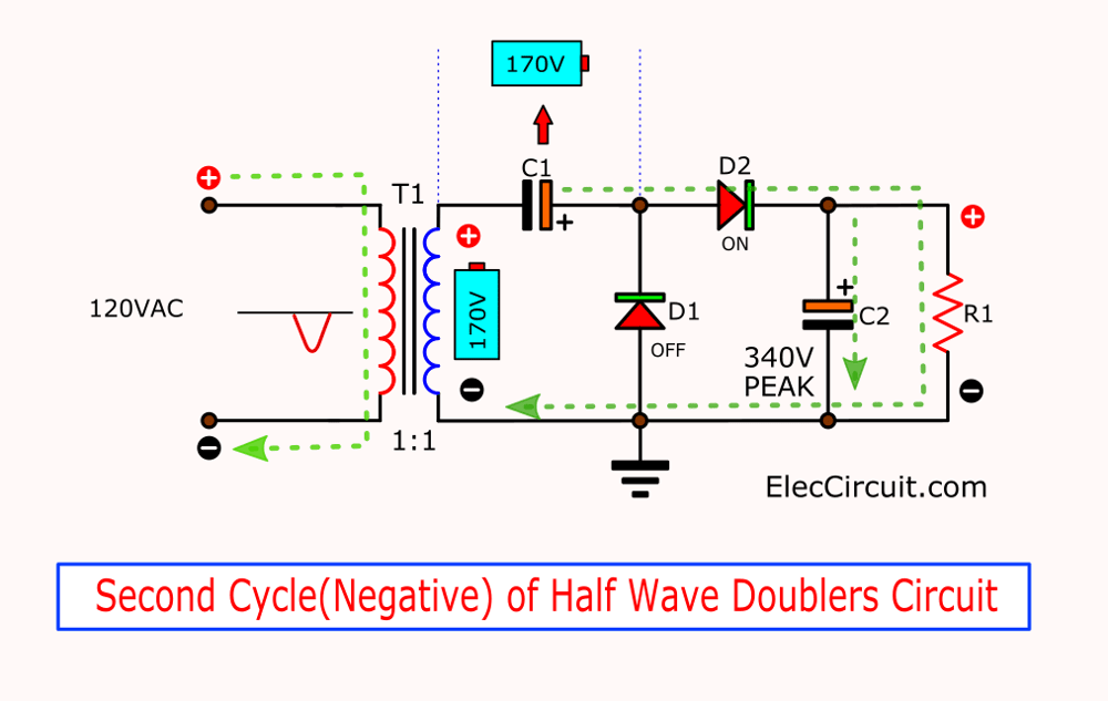
I created (and it is a simpler, actually, solution to implement) a half-wave doubler. It brings up the voltage up quite a bit, the radio consumtion is OK to not droop it too much, and it allows one of the AC INs to be the common negative.
With this (two diodes, two caps) I turned the radio on and I have:
258V instead of 220VDC as the rect. output (good), 202V or so in place of 180VDC as the filtered voltage output.
The filaments at 117VAC are exactly at 90V, so 3.3uF is perfect.
Now, the circuit is as such:

My C1 is 22uF and the output cap C2 is 16uF. During the charging the voltage distributes itself across these two as serialized. Therefore, I think, by decreasing the C1 I could adjust the output voltage down a bit. Which is what I am about to to.
This said, the radio works fine now.
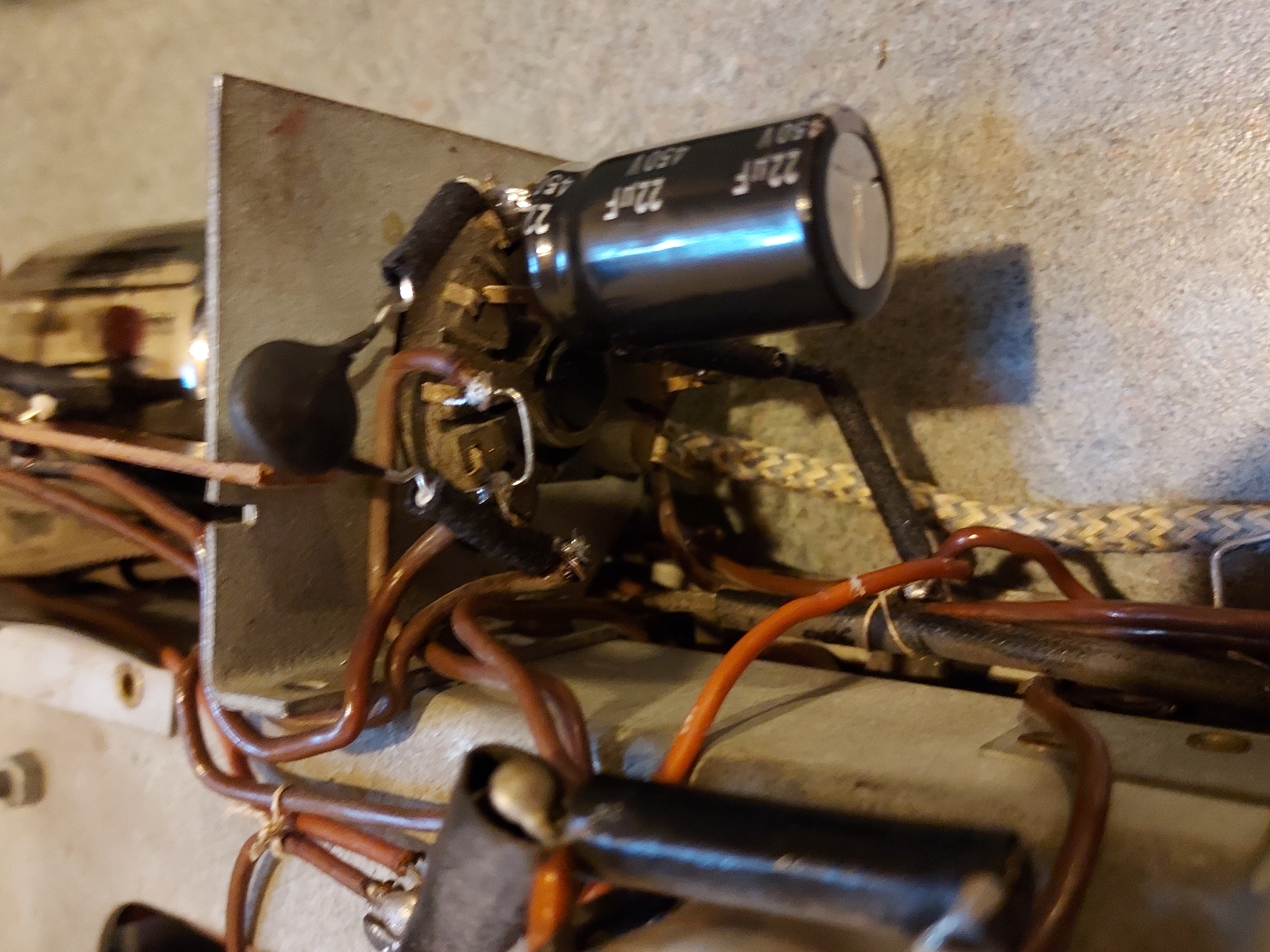
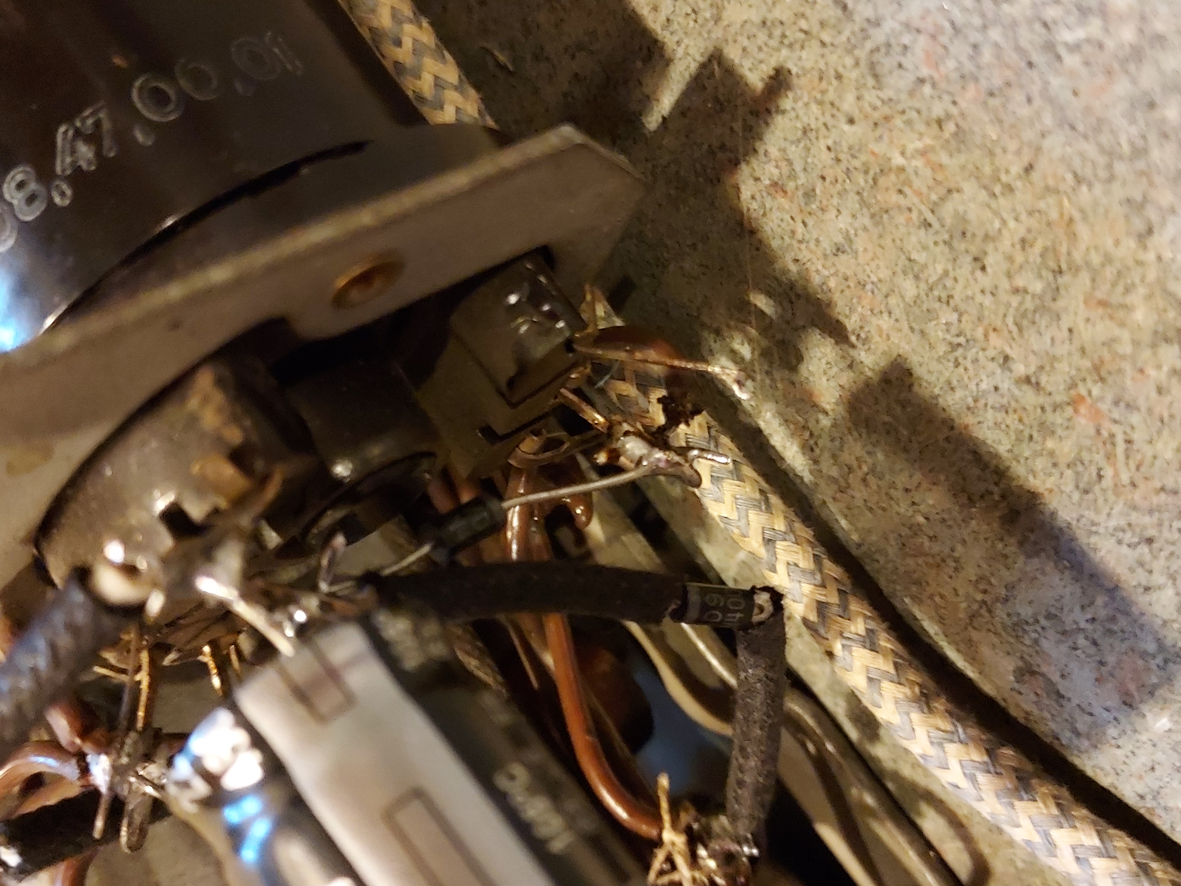
The concoction looks like this:


The rect tube is still there for looks with shorted filament.
Now, here's a video.
[Video: https://www.youtube.com/watch?v=AicnFfNcjFY]
Also, I decreased C1 cap to 10uF. My voltages now, when the radio warms up, are exactly where they should be:
225V first cap (220V in the schematic) and 178V filtered (180V in the sch).
Now to alignment. Tomorrow possibly.
Got it. I was not sure what this reference was in the context of the postings, but maybe Richard could explain, if maybe he meant Peter made something simialr.
Rod,
Well, I thought about it and then it probably would not. I did not try as I decided that there was a reason for referencing the filaments to the Rect negative.
So. What I've done is this:
I created (and it is a simpler, actually, solution to implement) a half-wave doubler. It brings up the voltage up quite a bit, the radio consumtion is OK to not droop it too much, and it allows one of the AC INs to be the common negative.
With this (two diodes, two caps) I turned the radio on and I have:
258V instead of 220VDC as the rect. output (good), 202V or so in place of 180VDC as the filtered voltage output.
The filaments at 117VAC are exactly at 90V, so 3.3uF is perfect.
Now, the circuit is as such:
My C1 is 22uF and the output cap C2 is 16uF. During the charging the voltage distributes itself across these two as serialized. Therefore, I think, by decreasing the C1 I could adjust the output voltage down a bit. Which is what I am about to to.
This said, the radio works fine now.
The concoction looks like this:
The rect tube is still there for looks with shorted filament.
Now, here's a video.
[Video: https://www.youtube.com/watch?v=AicnFfNcjFY]
Also, I decreased C1 cap to 10uF. My voltages now, when the radio warms up, are exactly where they should be:
225V first cap (220V in the schematic) and 178V filtered (180V in the sch).
Now to alignment. Tomorrow possibly.
People who do not drink, do not smoke, do not eat red meat will one day feel really stupid lying there and dying from nothing.


![[-] [-]](https://philcoradio.com/phorum/images/bootbb/collapse.png)


