06-13-2023, 09:04 PM
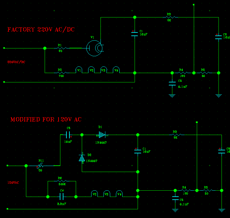
The 120VAC mod schematic. The PDF is a nicer one, but for a quick look I captured my CAD's screen.
I also added 500K resistor across that 3.3uF cap. It could be added across the input voltage also. Whichever is more convenient.
Note to folks who sub the ballasts with caps: same as across X-cap, a bleeder resistor is always needed. A 3.3uF cap is a large cap, and will store a lot of charge at potentially full input voltage peak.
500K will make for roughly 1.6 seconds discharge time and negligible electric effect while working, and negligfible power dissipation, hence the value.

A convenient place for me to put it is right across that cap.
PS. I also tried introducing X-Cap (0.47uF) across the AC lines, no effect. Y-cap already is there, 0.1uF between the Negative (lower AC line) and the GND, so no sense adding anything.
I also added 500K resistor across that 3.3uF cap. It could be added across the input voltage also. Whichever is more convenient.
Note to folks who sub the ballasts with caps: same as across X-cap, a bleeder resistor is always needed. A 3.3uF cap is a large cap, and will store a lot of charge at potentially full input voltage peak.
500K will make for roughly 1.6 seconds discharge time and negligible electric effect while working, and negligfible power dissipation, hence the value.
A convenient place for me to put it is right across that cap.
PS. I also tried introducing X-Cap (0.47uF) across the AC lines, no effect. Y-cap already is there, 0.1uF between the Negative (lower AC line) and the GND, so no sense adding anything.
People who do not drink, do not smoke, do not eat red meat will one day feel really stupid lying there and dying from nothing.


![[-] [-]](https://philcoradio.com/phorum/images/bootbb/collapse.png)


