Model 650 Tone Control Question
Posts: 13,776
Threads: 580
Joined: Sep 2005
City: Ferdinand
State, Province, Country: Indiana
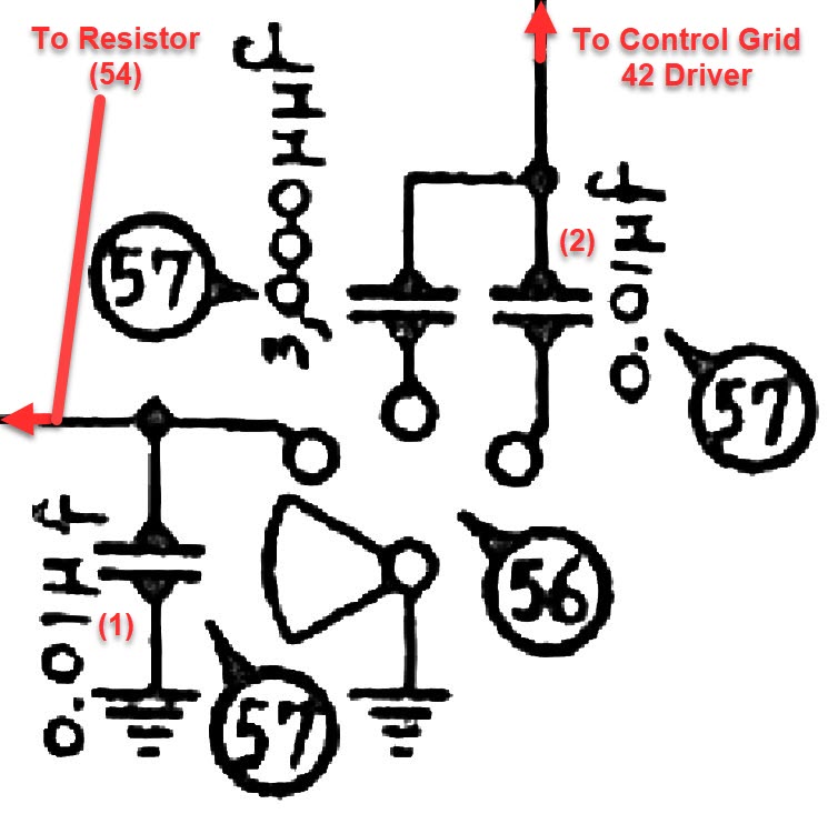
Here is a schematic drawing of your tone control. Notice the annotations added in red by me.

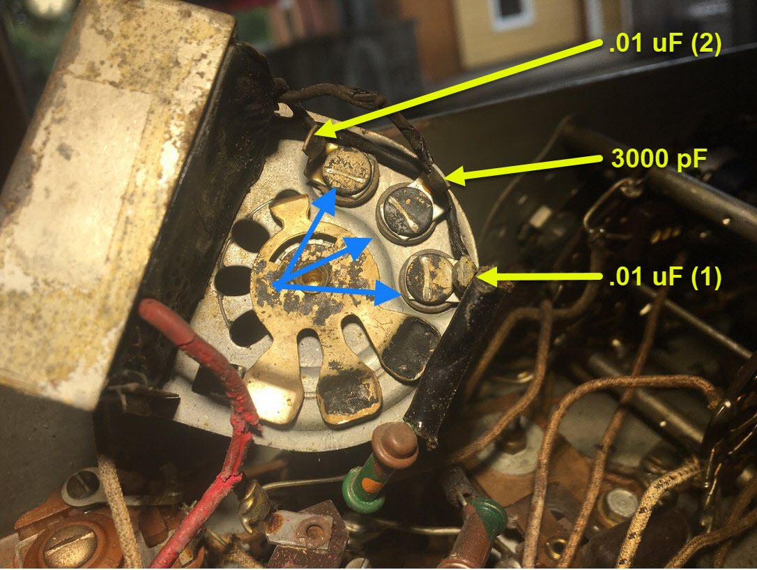
Now, in pictorial form, using your picture. Annotations in yellow added by me.

One end of the first .01 uF capacitor connects where you see .01 uF (1) in the photo. The other end of this capacitor runs, via a wire coming from the tone control body, to resistor (54).
One end of the 3000 pF (.003 uF, or if you prefer, 3 nF) connects as shown in the photo.
One end of the other .01 uF capacitor - .01 uF (2) - connects as shown.
The other ends of the 3000 pF cap and the .01 uF (2) cap connect together and run, via your red wire, to block (63) and to the control grid of the 42 driver tube.
--
Ron Ramirez
Ferdinand IN
Messages In This Thread
RE: Model 650 Tone Control Question - by Ron Ramirez - 06-27-2023, 02:39 PM
Users browsing this thread: 1 Guest(s)
|
|
Recent Posts
|
|
Model 80 Antenna Issue?
|
| Thanks Gary and Rod.
I also found an article in the Philco Repair Bench under Service Hints and Tips, about installi...Hamilton — 12:32 PM |
|
Model 80 Antenna Issue?
|
| Hello Hamilton, here is a little information found in our Philco Radio Library at the bottom of the Home page. Hope it ...GarySP — 11:28 AM |
|
Model 80 Antenna Issue?
|
| I did as you suggested and touching the middle of the volume control did nothing so the coil has to be rewound. Any idea...Hamilton — 10:19 AM |
|
1949 Motorola 5A9M
|
| This would be the second portable in the "other radios" forum where I have a similar one in my collection. I h...Arran — 12:41 AM |
|
Looking for any info: 1977 Ford-Philco Console Hi-Fi Turntable and Radio
|
| Hi PittsburgTost.
The record changer looks like a Garrard or BSR (Likely Garrard). The spindles just pull out and pu...MrFixr55 — 11:57 PM |
|
Looking for any info: 1977 Ford-Philco Console Hi-Fi Turntable and Radio
|
| Hello PittsburghToast ,
Welcome aboard and it looks like gary may have something for you !
now if I dig through my se...radiorich — 11:35 PM |
|
Model 80 Antenna Issue?
|
| You are kind of on the right path. You can touch the grid cap of the Detector/Oscillator 36 tube. I'm expecting a respon...RodB — 08:48 PM |
|
Looking for any info: 1977 Ford-Philco Console Hi-Fi Turntable and Radio
|
| Welcome to the Phorum, PittsburghToast! I found an old thread that my interest you regarding the quality and worth of P...GarySP — 08:48 PM |
|
Looking for any info: 1977 Ford-Philco Console Hi-Fi Turntable and Radio
|
| Welcome to the Phorum!
:wave:
We do not have anything on that unit in our digital library. There is a Sam's Photof...klondike98 — 08:47 PM |
|
Model 80 Antenna Issue?
|
|
I’ve replaced all the caps and resistors and the radio is working but minimal volume unless I put my hand near the re...Hamilton — 08:24 PM |
|
Who's Online
|
| There are currently no members online. |

|
 
|


![[-] [-]](https://philcoradio.com/phorum/images/bootbb/collapse.png)


