07-04-2023, 12:40 AM
Hi Hamilton,
Regarding voltages and pinouts for the 42 "Driver" and the 2 42 "Push Pull" Output tubes:
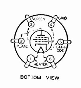
Below is a diagram of the connections to the 42 as viewed from the underside of the chassis. Please note that the heater connections, Pins 1 and 6 are larger in diameter than the other pins.

Below is a copy of the Tung Sol Spec Sheet for the 6F6, 42 and 2A5. Other than pinouts (6F6) and heater voltage, current (2A5), these tubes have the same characteristics. This lists "maximum" voltages. For the output stage use Class AB, triode connected, cathode bias.
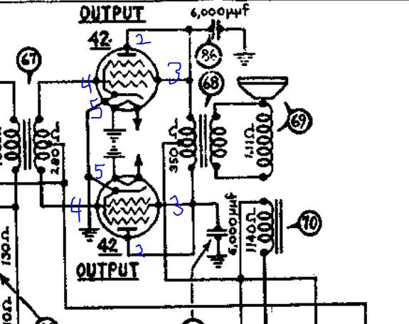
Below is the section of the Philco 650 schematic showing the output stage only, for clarity.

The Philco 650 Schematic shows all 3 "42"s connected as triodes (This was common; RCA did this in several sets using 2A5s). Of course, Philco had more than 1 variation for several chassis and these may be connected as pentodes. However, the plate and screen voltages should substantially match between the 2 output tubes. In addition, the control grid voltages should also substantially match between the 2 tubes.
Hope this helps!
Regarding voltages and pinouts for the 42 "Driver" and the 2 42 "Push Pull" Output tubes:
Below is a diagram of the connections to the 42 as viewed from the underside of the chassis. Please note that the heater connections, Pins 1 and 6 are larger in diameter than the other pins.
Below is a copy of the Tung Sol Spec Sheet for the 6F6, 42 and 2A5. Other than pinouts (6F6) and heater voltage, current (2A5), these tubes have the same characteristics. This lists "maximum" voltages. For the output stage use Class AB, triode connected, cathode bias.
Below is the section of the Philco 650 schematic showing the output stage only, for clarity.
The Philco 650 Schematic shows all 3 "42"s connected as triodes (This was common; RCA did this in several sets using 2A5s). Of course, Philco had more than 1 variation for several chassis and these may be connected as pentodes. However, the plate and screen voltages should substantially match between the 2 output tubes. In addition, the control grid voltages should also substantially match between the 2 tubes.
- Power radio down and allow plenty of time for the "caps" to discharge.
- Remove all 3 42s. Ohm between Pin 2 and 3 of each tube. It should read a dead short. In addition, you should see that for each 42, pins 2 and 3 should be jumpered together. If this is not the case, respond in a post.
- Ohm between pin 2 (plate) of one 42 Output tube and pin 2 (plate)0of the other 42 Output tube. The resistance should be about 350 Ohm. Ohm between Pin 2 of one 42 Output and the center tap of the output transformer. it should be roughly half the "plate to plate" resistance. Ohm between the center tap of the output transformer and pin 2 of the other 42 Output tube. it should be close to the previous measurement and the sum should be the same as the reading between each output tube's pin 2.
- Ohm between pin 4 (grid) of one output tube and pin 4 (grid) of the other output tube. It should read 280 Ohm. Read between each tube and the center tap of the interstage transformer as in the previous step. Each reading should be roughly half of the "grid to grid" reading and the sum of the 2 readings should substantially match the grid to grid reading.
- Ohm between pin 5 of the 2 output tubes and chassis ground. There should be a dead short.
- If all of these readings pan out, the plate and screen voltage readings between the 2 output tubes should match. Let me know the outcome.
Hope this helps!
"Do Justly, love Mercy and walk humbly with your God"- Micah 6:8
"Let us begin to do good"- St. Francis
Best Regards,
MrFixr55


![[-] [-]](https://philcoradio.com/phorum/images/bootbb/collapse.png)


