Thread Rating:
  • 0 Vote(s) - 0 Average
  • 1
  • 2
  • 3
  • 4
  • 5

41-250 Restoration
#34

Hi Bridkarl, 

Thanks for the pictures, they are helpful.  On first view, if the 16 uF cap appears to be soldered to pin 8 of the 5Y3.  If this is the case, then the 2 caps may be swapped.  This is not horrible, it is just not per the schematic.  Make the following checks:
  • Verify resistance of the Candohm.
  • Verify that the side that reads 15 Ohm is grounded and the side that reads 146 Ohm is connected to the center tap of the HV secondary.
  • With the speaker connected, verify resistance approximately 1100 Ohm between the +Terminal of the 16 uF cap and  the 12 uF cap.

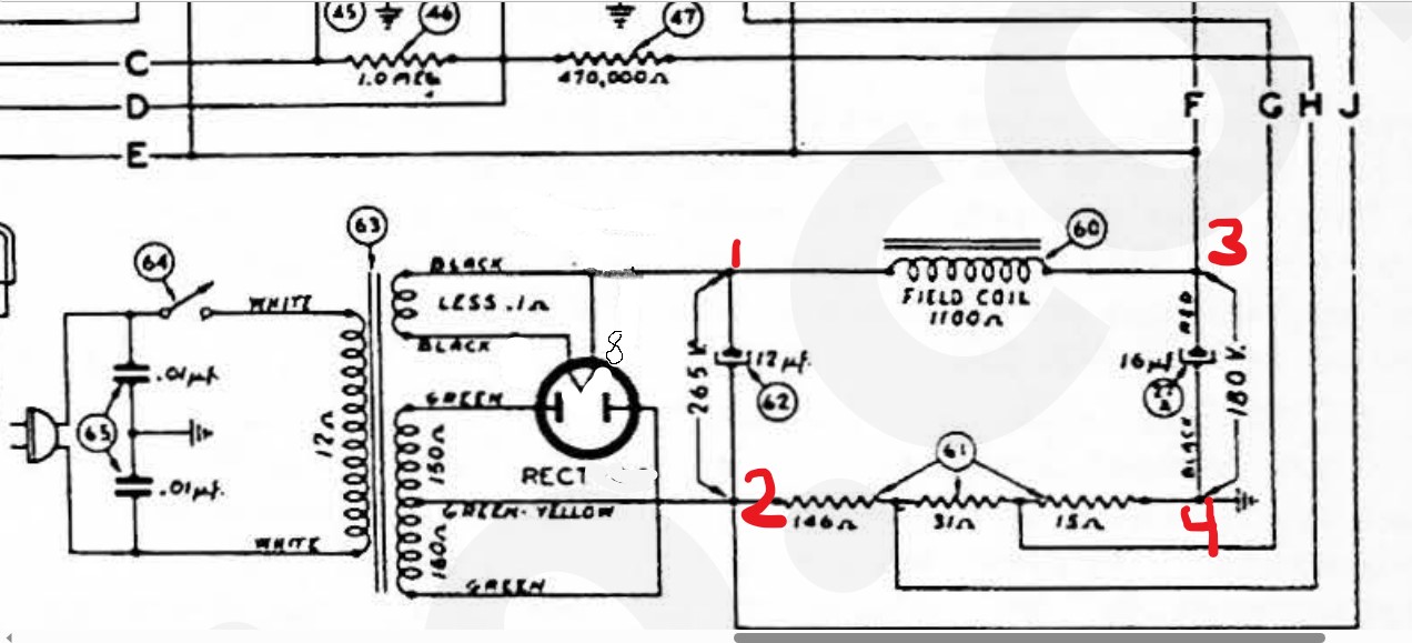
I modified the schematic for you to reflect a 5Y3.  Refer to the pic attached below:
   
Note that only the 5Y3 heater and HV windings are shown. The heater winding for the other tubes are not shown

Note the red numbers for the following instructions:
    1. This connection is the junction of the 5Y3 filament at Pin 8, the input to the field coil and the + terminal of the 12uf cap, (#62 on the schematic).
    2. This connection is the junction of the - terminal of the 12uF cap (#62), the center tap of the HV secondary winding of the power transformer (This is the winding that feeds the plates of the 5Y3), the 146 Ohm end of the Candohm and Line J. (Line J connects this most negative point of the power supply to the grid bias resistors of the two 41 output tubes.
    3. This connection is the junction of the + terminal of the 16uF cap (#27A) and the B+, Lines E, F to the rest of the radio, feeding the audio output transformer, the 41 screen grid, the 3700 Ohm resistor to the other 41 screen grid, the IF input and output transformer primaries, the plate load resistor for the 1st AF amp, and a voltage divider consisting of resistors #28 and 26.
    4. This connection is the junction of the - terminal of the 16uF cap (#27A), the 15 Ohm end of the Candohm and chassis ground.
    5. See the next diagram.  
       
         This is + terminal of the 8uF cap (#27) and the junctions of resistors #28 and 26. This point provides the B+ to the       mixer tube and the screen voltage for the IF tube, and, through the other leg of resistor #26, the 40VDC to the
         oscillator plate.  The - terminal of the 8uF cap is connected to chassis ground.

    Voltage between points 1 and 2 should be about 260VDC.  Voltage between 3 and 4 should be about 180VDC.

    Hope this helps!


Messages In This Thread
41-250 resistor size - by bridkarl - 08-01-2023, 07:56 PM
RE: 41-250 resistor size - by RodB - 08-01-2023, 08:38 PM
RE: 41-250 resistor size - by bridkarl - 08-01-2023, 08:53 PM
RE: 41-250 resistor size - by klondike98 - 08-01-2023, 09:58 PM
RE: 41-250 resistor size - by MrFixr55 - 08-01-2023, 10:54 PM
RE: 41-250 resistor size - by bridkarl - 08-02-2023, 08:13 AM
RE: 41-250 resistor size - by JimSirt - 08-02-2023, 12:21 PM
RE: 41-250 resistor size - by bridkarl - 08-02-2023, 12:48 PM
RE: 41-250 resistor size - by klondike98 - 08-03-2023, 12:20 AM
RE: 41-250 resistor size - by MrFixr55 - 08-03-2023, 09:20 PM
462ron - by 462ron - 08-04-2023, 07:00 AM
RE: 41-250 resistor size - by bridkarl - 08-04-2023, 10:13 PM
RE: 41-250 resistor size - by bridkarl - 08-04-2023, 10:45 PM
RE: 41-250 resistor size - by bridkarl - 08-05-2023, 12:40 PM
RE: 41-250 resistor size - by bridkarl - 08-05-2023, 03:04 PM
RE: 41-250 resistor size - by RodB - 08-05-2023, 06:05 PM
RE: 41-250 resistor size - by bridkarl - 08-05-2023, 09:14 PM
RE: 41-250 resistor size - by bridkarl - 08-06-2023, 11:22 AM
RE: 41-250 resistor size - by Ron Ramirez - 08-06-2023, 01:16 PM
RE: 41-250 resistor size - by MrFixr55 - 08-06-2023, 01:58 PM
RE: 41-250 resistor size - by bridkarl - 08-06-2023, 02:00 PM
RE: 41-250 resistor size - by Ron Ramirez - 08-06-2023, 02:13 PM
RE: 41-250 resistor size - by MrFixr55 - 08-06-2023, 02:34 PM
RE: 41-250 resistor size - by bridkarl - 08-06-2023, 02:56 PM
RE: 41-250 resistor size - by MrFixr55 - 08-06-2023, 02:56 PM
RE: 41-250 resistor size - by Ron Ramirez - 08-06-2023, 03:01 PM
RE: 41-250 resistor size - by bridkarl - 08-06-2023, 03:18 PM
RE: 41-250 resistor size - by MrFixr55 - 08-06-2023, 03:21 PM
RE: 41-250 resistor size - by bridkarl - 08-06-2023, 08:35 PM
RE: 41-250 resistor size - by bridkarl - 08-07-2023, 01:04 AM
RE: 41-250 resistor size - by RodB - 08-07-2023, 07:47 AM
RE: 41-250 resistor size - by bridkarl - 08-07-2023, 08:20 AM
RE: 41-250 resistor size - by MrFixr55 - 08-07-2023, 01:16 PM
RE: 41-250 resistor size - by bridkarl - 08-07-2023, 01:47 PM
RE: 41-250 resistor size - by MrFixr55 - 08-07-2023, 04:48 PM
RE: 41-250 resistor size - by bridkarl - 08-07-2023, 07:20 PM
RE: 41-250 resistor size - by MrFixr55 - 08-07-2023, 09:55 PM
RE: 41-250 resistor size - by bridkarl - 08-08-2023, 12:29 PM
RE: 41-250 resistor size - by MrFixr55 - 08-08-2023, 02:58 PM
RE: 41-250 resistor size - by bridkarl - 08-08-2023, 11:12 PM
RE: 41-250 resistor size - by MrFixr55 - 08-09-2023, 10:19 AM
RE: 41-250 resistor size - by bridkarl - 08-09-2023, 10:40 AM
RE: 41-250 resistor size - by MrFixr55 - 08-09-2023, 11:29 AM
RE: 41-250 resistor size - by bridkarl - 08-09-2023, 11:59 AM
RE: 41-250 resistor size - by Ron Ramirez - 08-09-2023, 12:26 PM
RE: 41-250 resistor size - by bridkarl - 08-09-2023, 01:22 PM
RE: 41-250 resistor size - by Radioroslyn - 08-09-2023, 11:03 PM
RE: 41-250 resistor size - by bridkarl - 08-10-2023, 12:23 PM
RE: 41-250 resistor size - by MrFixr55 - 08-10-2023, 09:23 PM
RE: 41-250 resistor size - by bridkarl - 08-10-2023, 09:30 PM
RE: 41-250 Now fixed!!! - by bridkarl - 08-14-2023, 07:59 PM
RE: 41-250 Restoration - by admin - 08-16-2023, 10:14 AM
RE: 41-250 Restoration - by Ron Ramirez - 08-16-2023, 10:20 AM
RE: 41-250 Restoration - by bridkarl - 08-16-2023, 01:28 PM
RE: 41-250 Restoration - by klondike98 - 08-17-2023, 02:32 PM
RE: 41-250 Restoration - by bridkarl - 08-17-2023, 07:46 PM
RE: 41-250 Restoration - by Ron Ramirez - 08-17-2023, 07:52 PM
RE: 41-250 Restoration - by bridkarl - 08-17-2023, 08:02 PM
RE: 41-250 Restoration - by Ron Ramirez - 08-17-2023, 08:05 PM
RE: 41-250 Restoration - by bridkarl - 08-17-2023, 08:46 PM
RE: 41-250 Restoration - by bridkarl - 08-18-2023, 12:11 PM
RE: 41-250 Restoration - by MrFixr55 - 08-18-2023, 09:47 PM
RE: 41-250 Restoration - by bridkarl - 08-19-2023, 07:42 AM
RE: 41-250 Restoration - by MrFixr55 - 08-19-2023, 07:56 AM
RE: 41-250 Restoration - by bridkarl - 08-25-2023, 03:16 PM
RE: 41-250 Restoration - by bridkarl - 08-25-2023, 04:34 PM
RE: 41-250 Restoration - by Paul Philco322 - 08-25-2023, 08:17 PM
RE: 41-250 Restoration - by bridkarl - 08-25-2023, 08:46 PM
462ron - by 462ron - 08-26-2023, 07:59 AM
Location of 1.8 ohm resistor 41-250 - by bridkarl - 08-02-2023, 08:46 PM


Users browsing this thread: 1 Guest(s)
[-]
Recent Posts
Samlex heavy-Duty bench supply filter question
Hello Everyone, I have one of my Heavy-duty bench powersuplies made by Samlex it's 13.8 volt dc 20-25 amp supply. What I...radiorich — 11:24 PM
Looking for place to donate unique Philco Philco J-1930 Prototype
It's a Glaser Sears changer which Philco's engineers thought was an upgrade over a VM, but in retrospect I'd prefer the ...jeibner — 10:39 PM
AC/DC Transformer-less Sets
Joseph, Thank you for the confirmation. I knew that there must be more to the Transformer-less AC/DC radios than the ...PeterN — 10:30 PM
AC/DC Transformer-less Sets
Good evening, folks. Power station engineer here! The east coast had pockets of DC-only power well into the twentieth...jrblasde — 10:11 PM
AC/DC Transformer-less Sets
Model 40 does not have a rectifier, so it would be a DC only model. This however does not say anything about using...morzh — 08:01 PM
AC/DC Transformer-less Sets
I was wondering if anyone knows if these AC/DC transformer-less sets were actually used on 110v DC anywhere, and when. ...PeterN — 06:35 PM
Looking for place to donate unique Philco Philco J-1930 Prototype
Given the 1960s vintage, it is likely that the cartridge is ceramic, likely more stable. The changer looks like a Voice...MrFixr55 — 05:03 PM
Jackson 665 j2 schematic request
FIXED!daveone23 — 03:55 PM
Bakelite crack repair - what is best epoxy?
Thanks everyone. I appreciate you sharing your experience and looks like I'll work with the 24 hr two part clear epoxy....de371 — 10:25 PM
Jackson 665 j2 schematic request
Without a schematic its going to be hard tracing the wire wound spool resistors.daveone23 — 05:21 PM

[-]
Who's Online
There are currently 4226 online users. [Complete List]
» 1 Member(s) | 4225 Guest(s)
Avatar

>