08-27-2024, 09:54 PM
Today I have finished recapping.
The last two days' evenings I spent rebuilding the electrolytics.
First I had to drain them. I drilled two small holes diametrically across the bottom of both caps, one to drain the liquid and the other to let the air in.
After that I cut them open, gutted and soaked in white vinegar to get rid of some deposits and oxidation.
Then I rinsed and dried them, and after all this I started the "gefilte cap" dish.
First prep the 12uF cap: serialized two 22uF high-ripple Panasonic capacitors (22uF 450V, 560mA ripple at 120Hz).The resulting capacitance is 11uF, close enough.
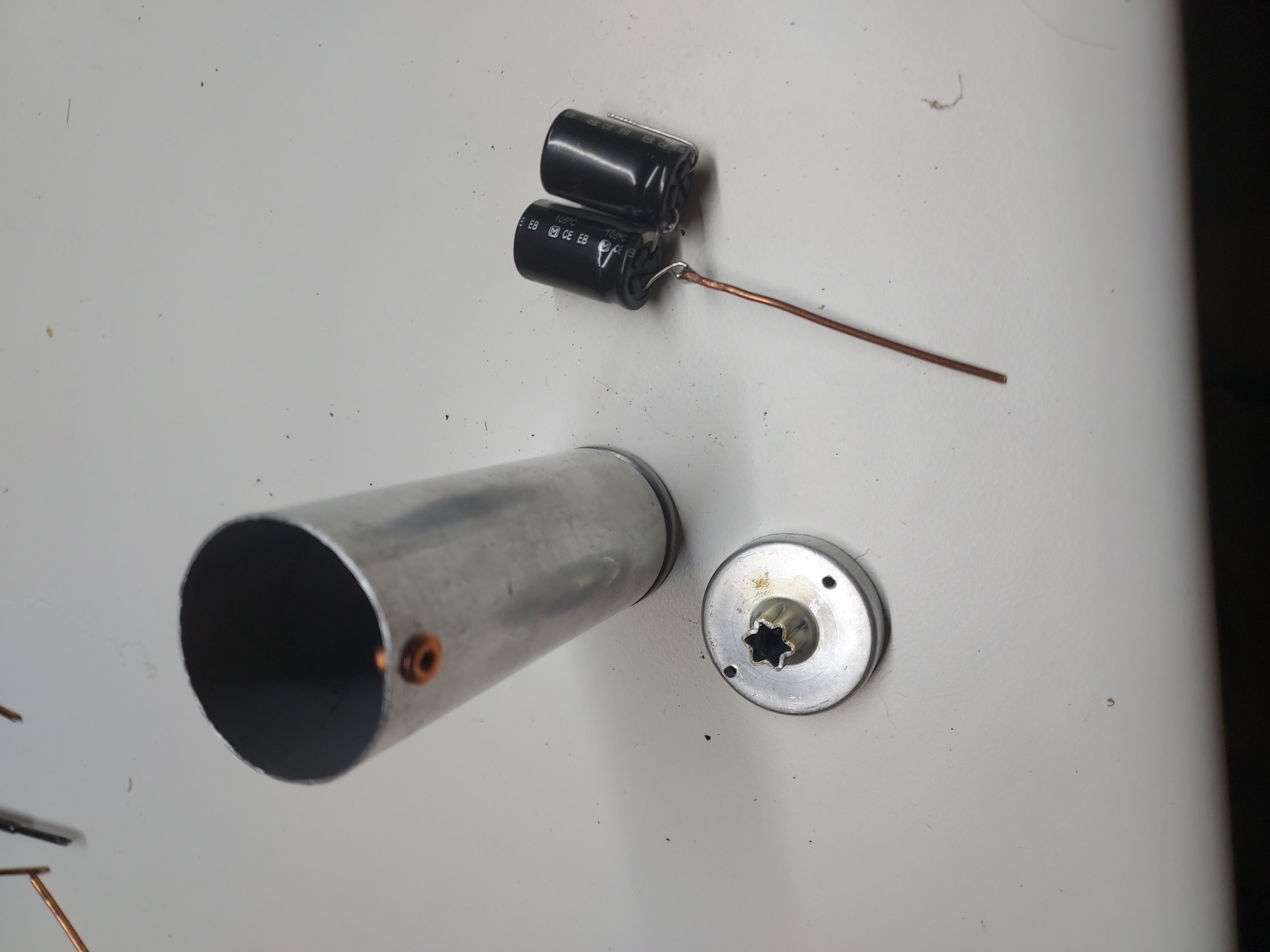
Then wrap it in fish paper (to keep the cases from the shell), push into the shell, and insert two spacers to stabilize it inside the shell (also made from fish paper, a simple roll).
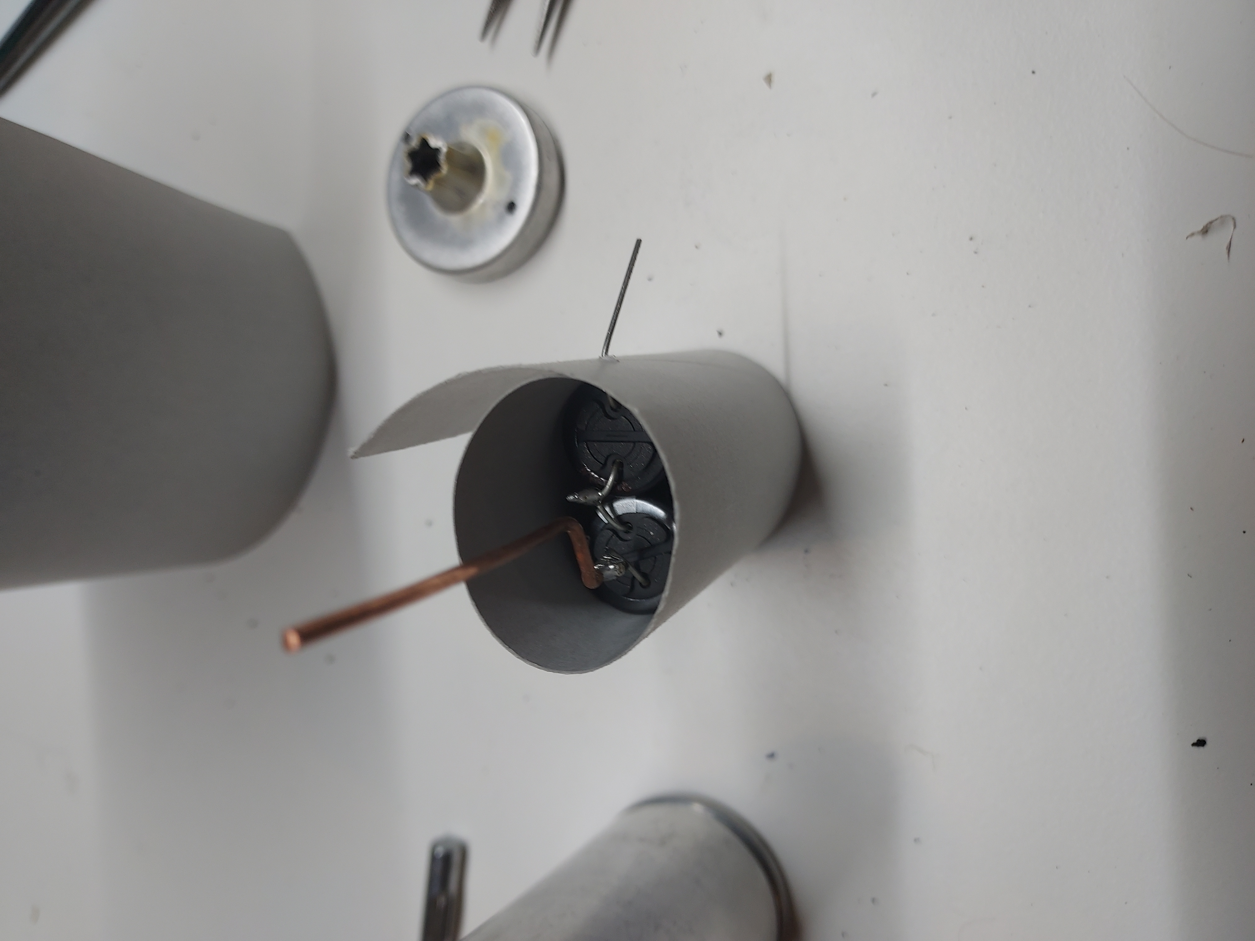
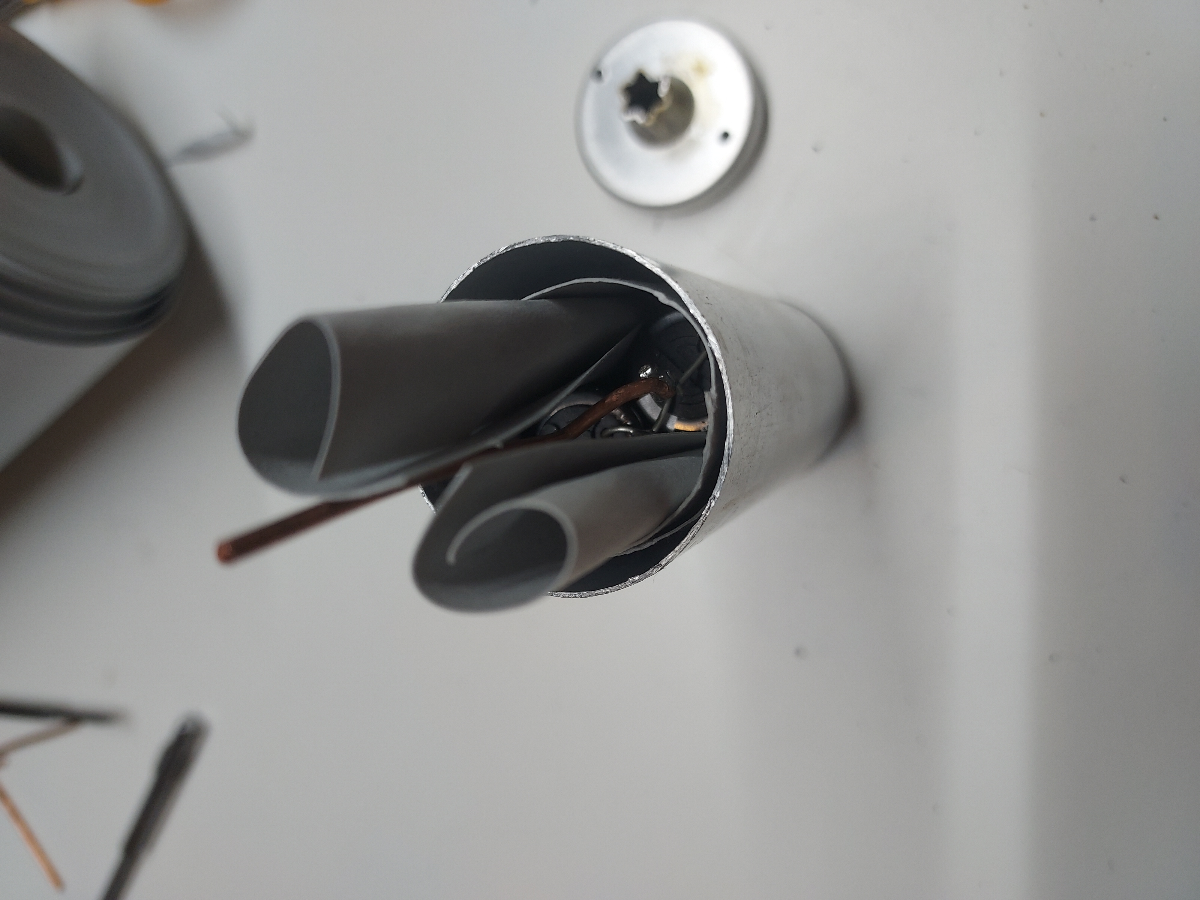
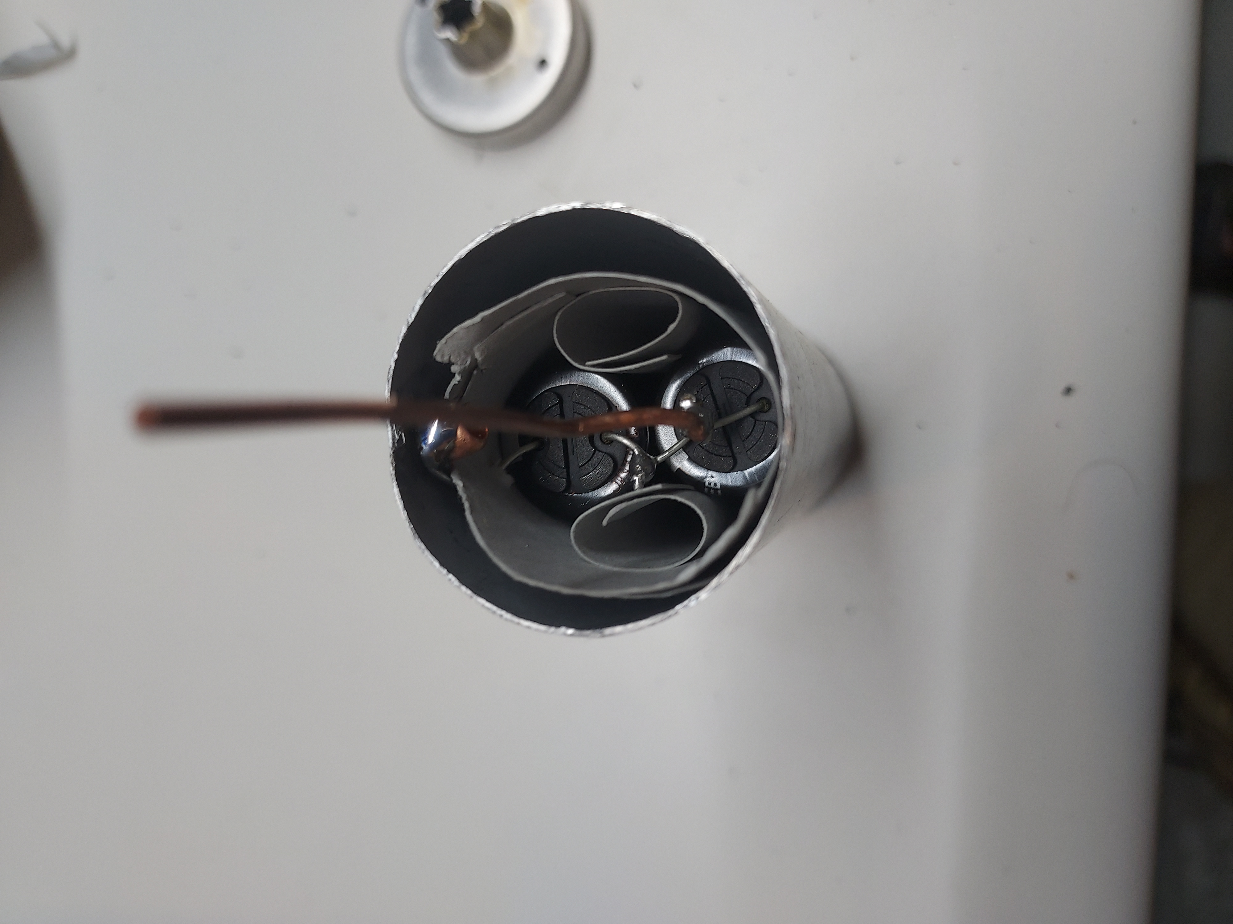
Then I put a copper rivet at the side of the shell, and soldered the negative lead to it.
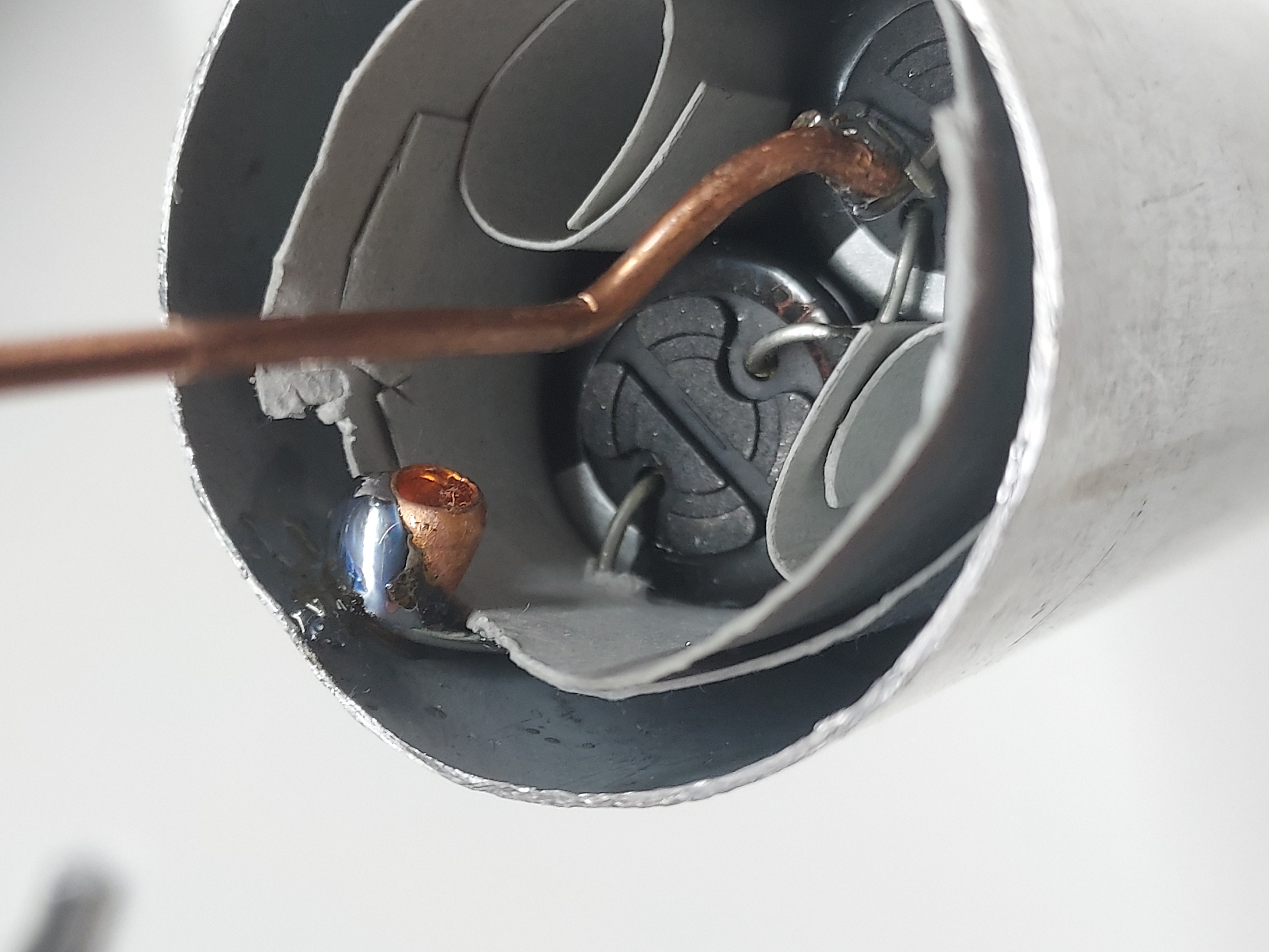
This cap is now ready for epoxying the bottom back to it.
Now the 4uF cap. This is the second filter cap, and it could be larger than the original, so I use a high ripple 10uF 450V cap (170mA). This cap does not experience lots of ripple as it is preceded by the inductance (Field coil), so for all I care, it could be just a GP electrolytic.
Unlike the first cap, which is insulated from the chassis, this one uses the shell as the GND, and so the bottom of the shell could benefit from being solid, so the most natural place to cut is the cap's groove at the top.
Now I had to think of how to best connect the minus of the cap to the shell, so what I did was manufacturing a copper foil ring with a solder terminal, which would receive the inner cap's negative through a hole in the shell, while itself being between the shell's bottom and the chassis.
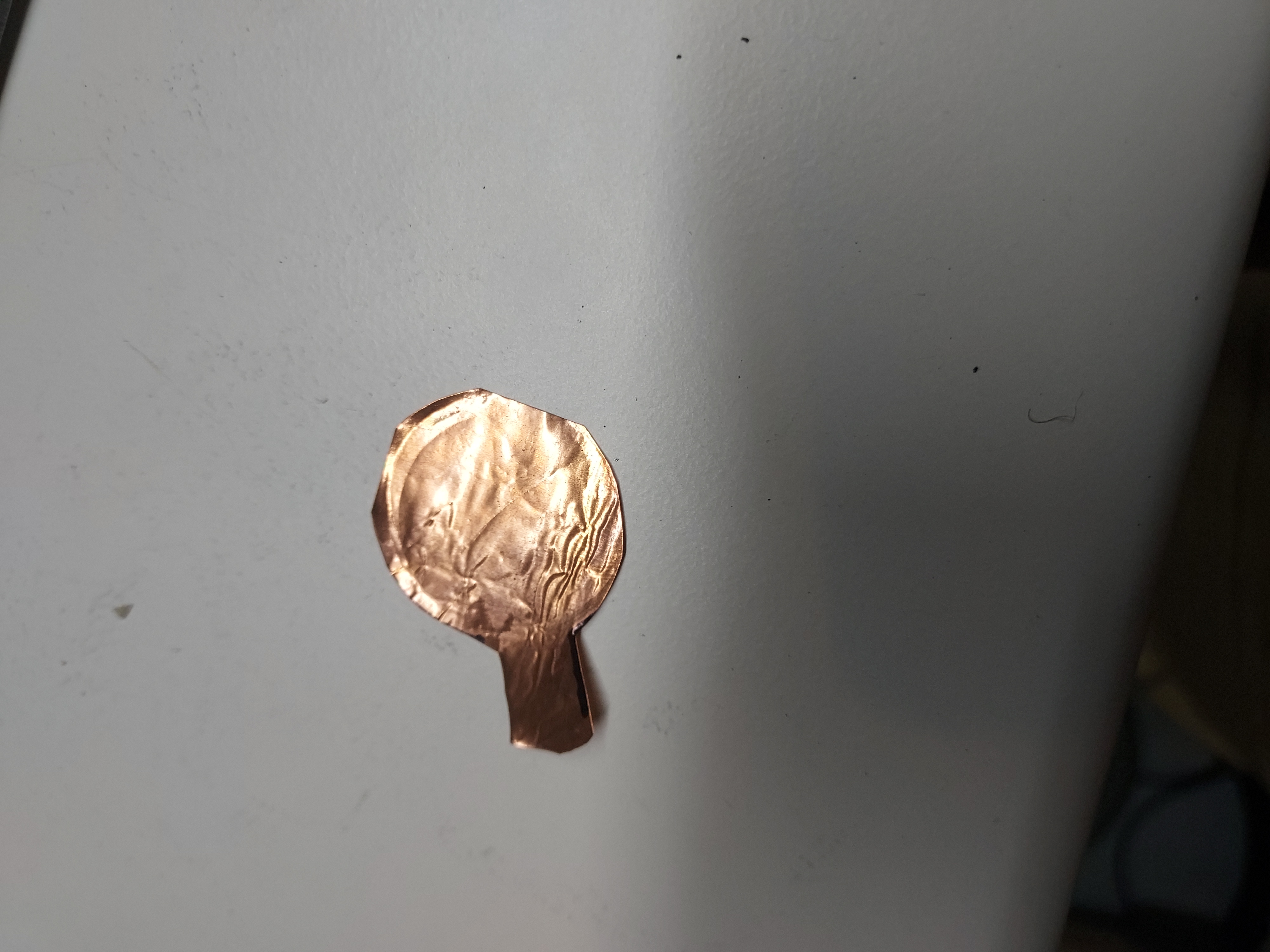
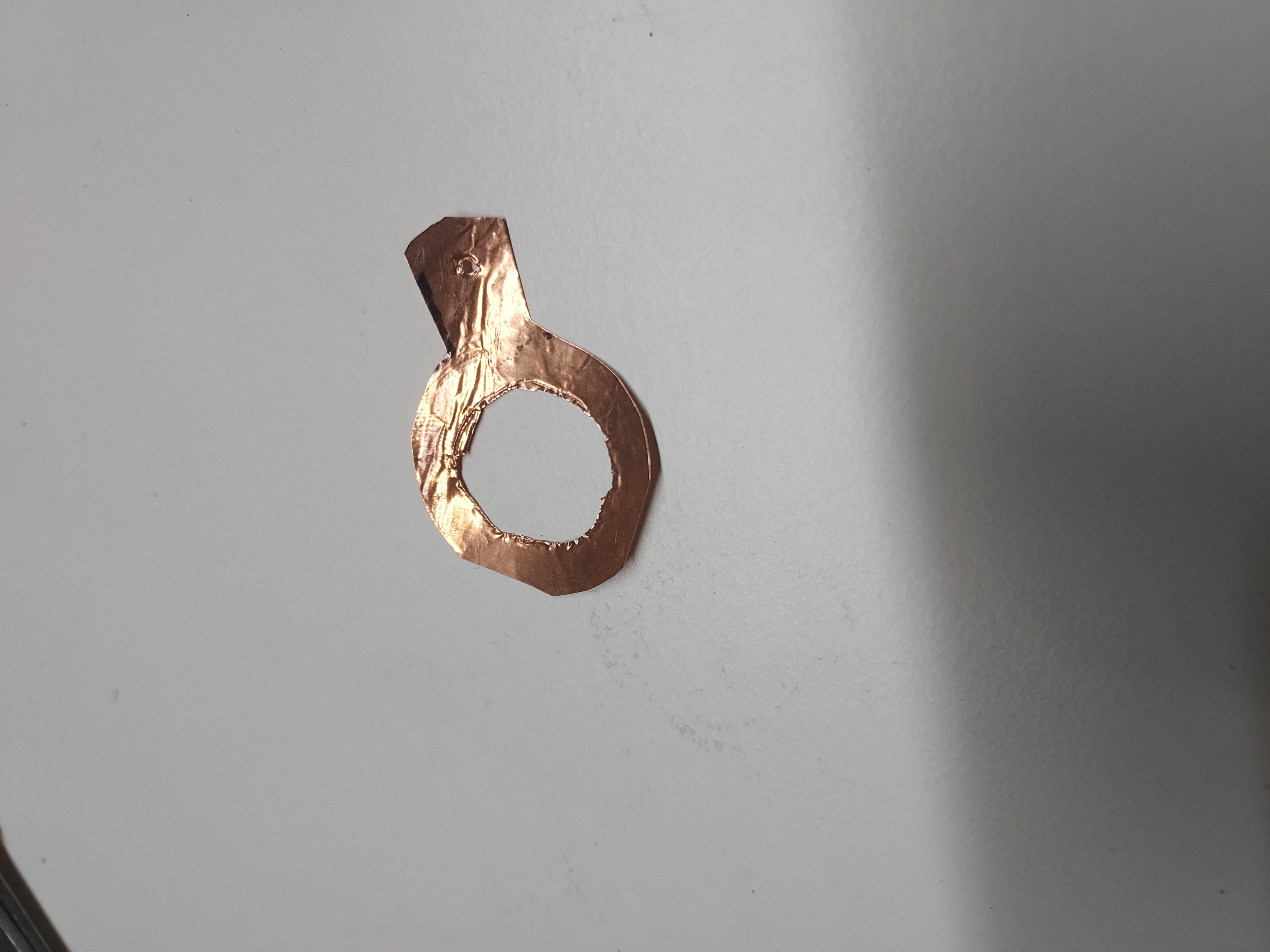
I soldered tug wires to the cap, to pull the leads through.
Then I trimmed and soldered the side lead.
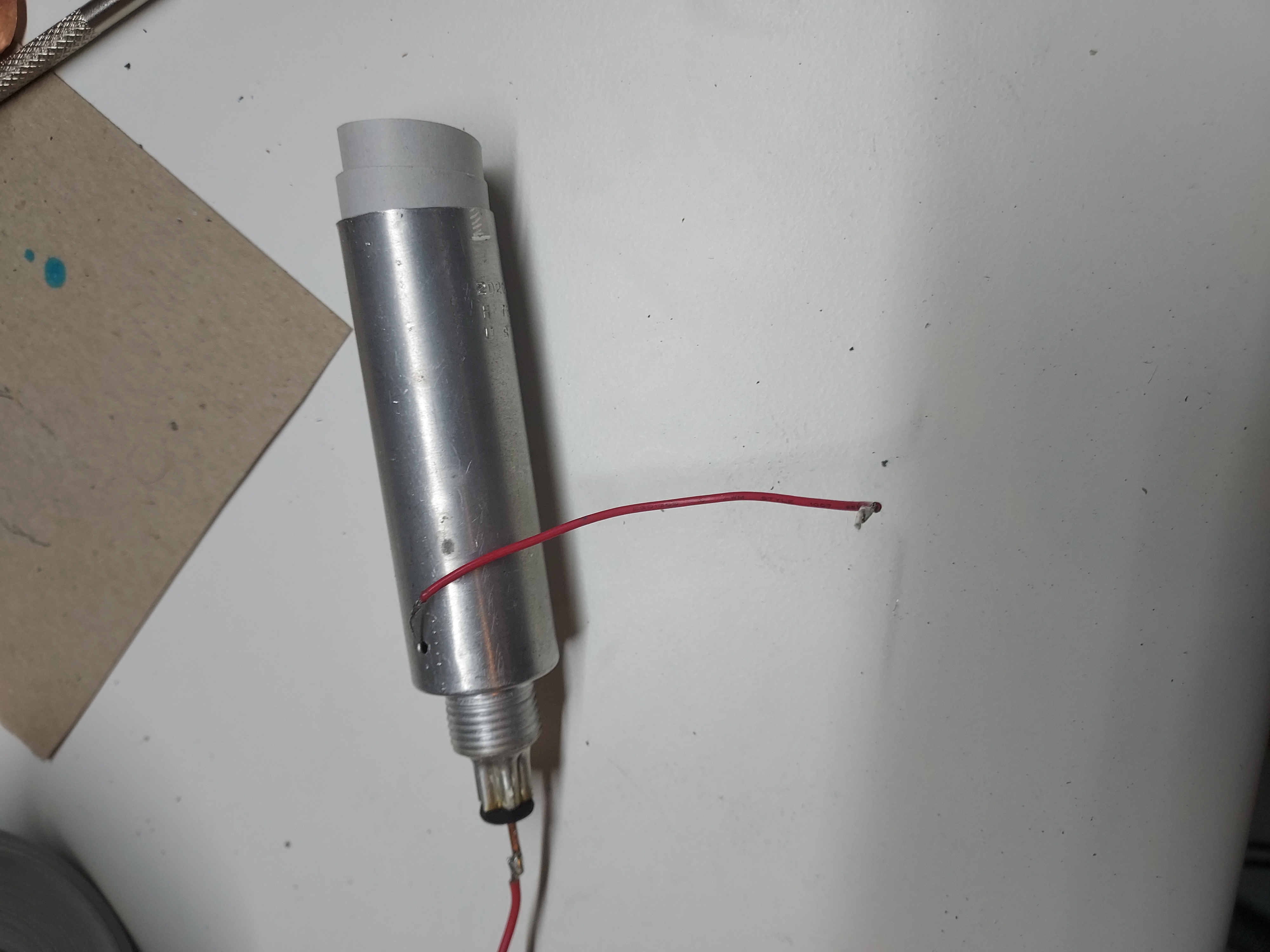
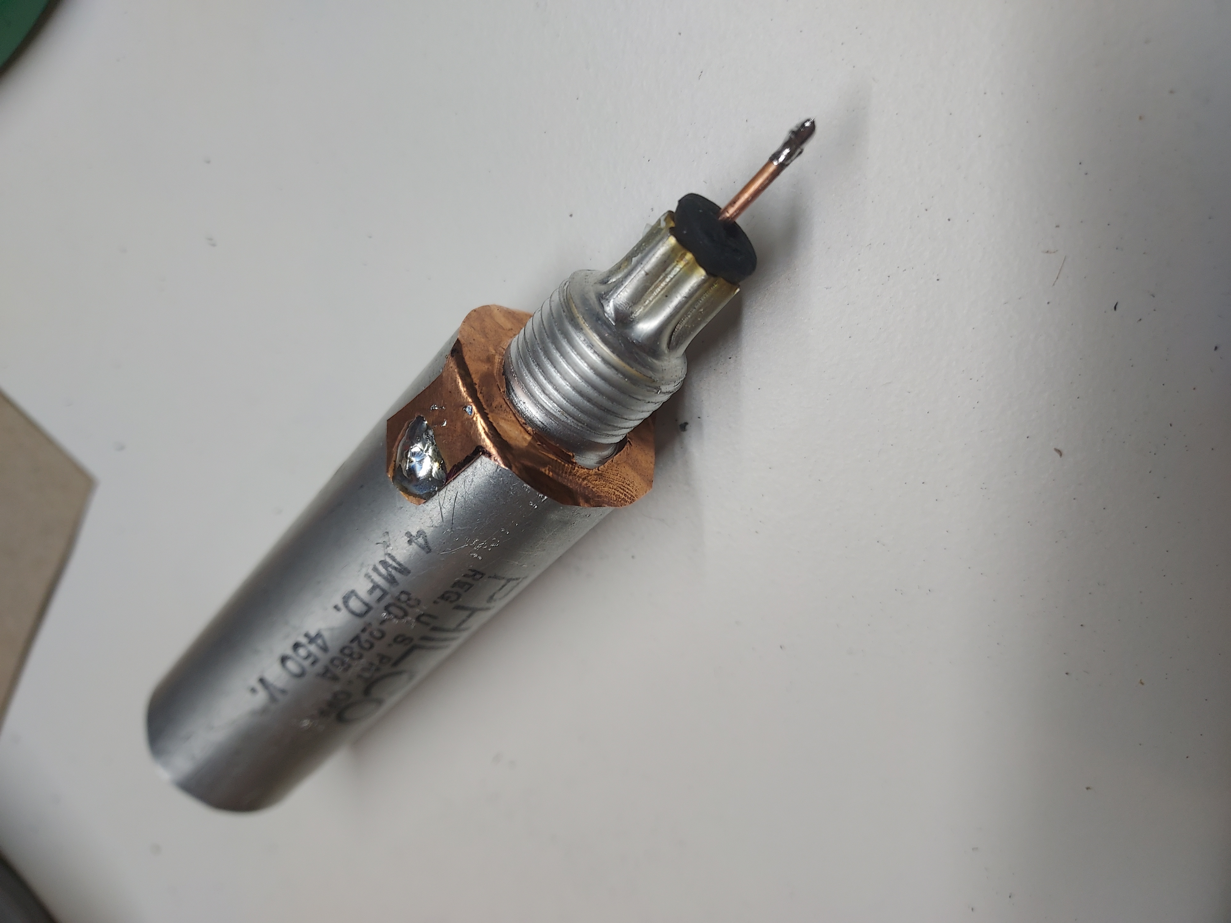
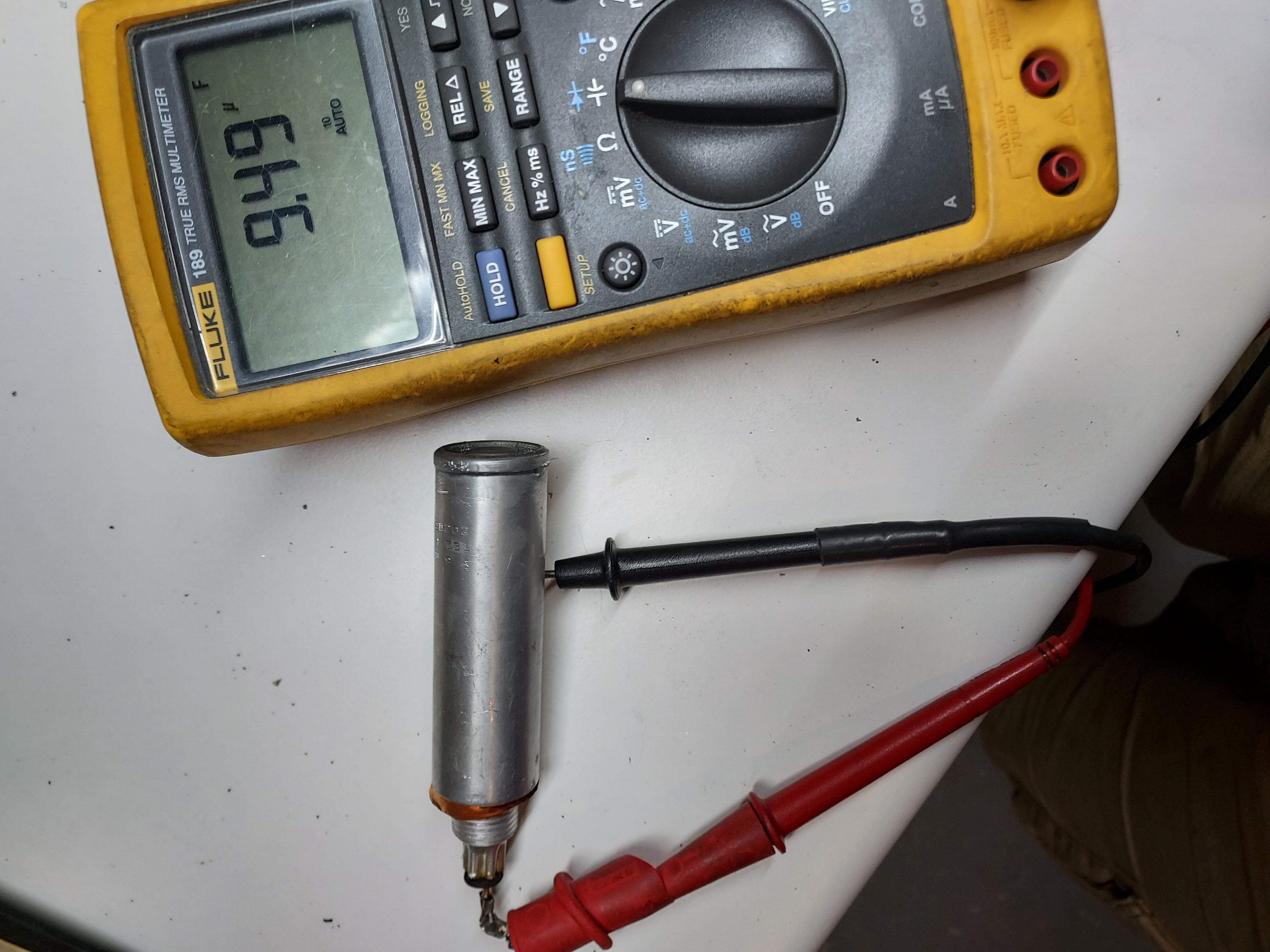
Then I measured the capacitance.
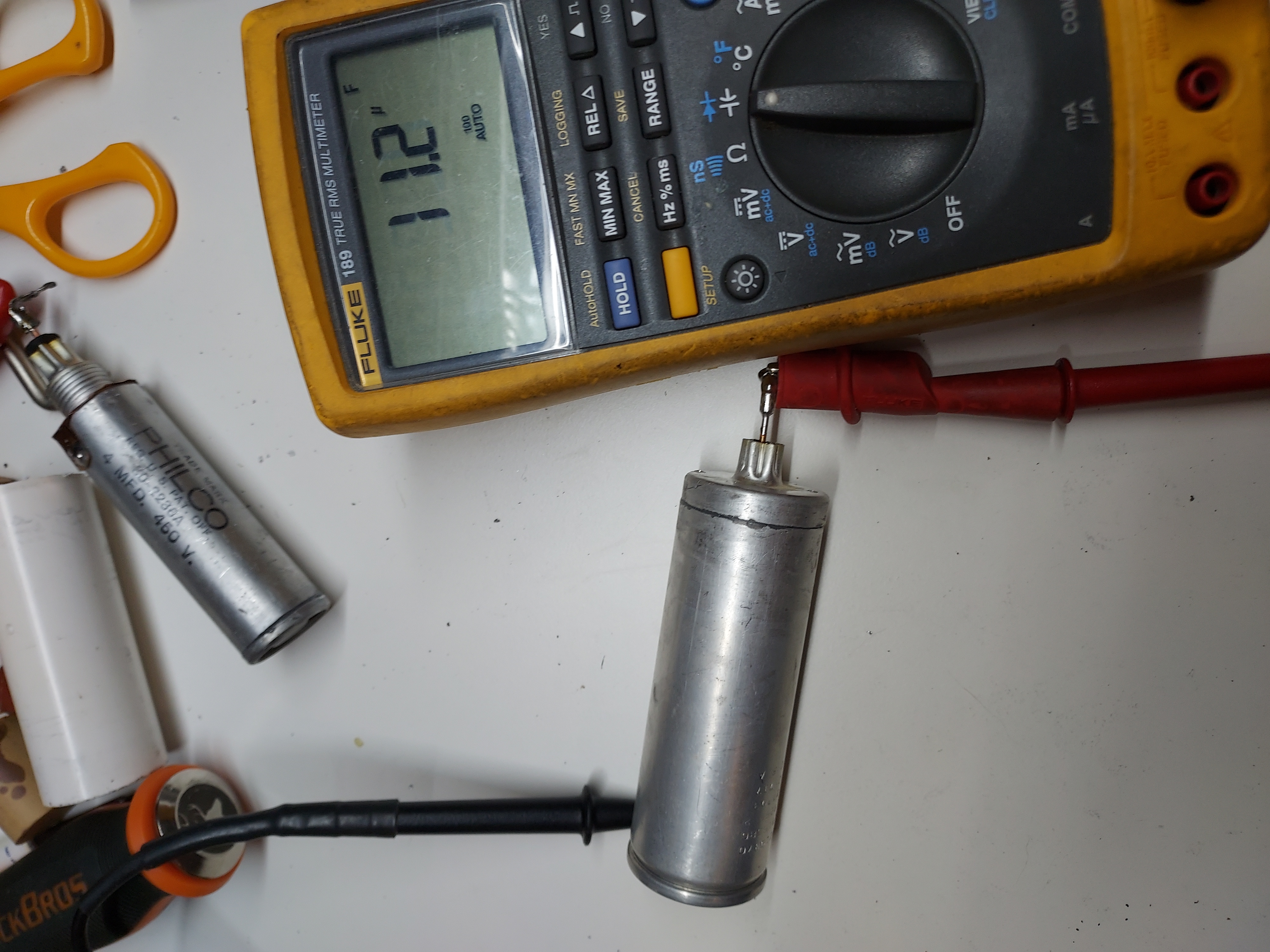
This is how the caps look in citu, and the whole chassis after I also changed some broken antenna/GND wires.
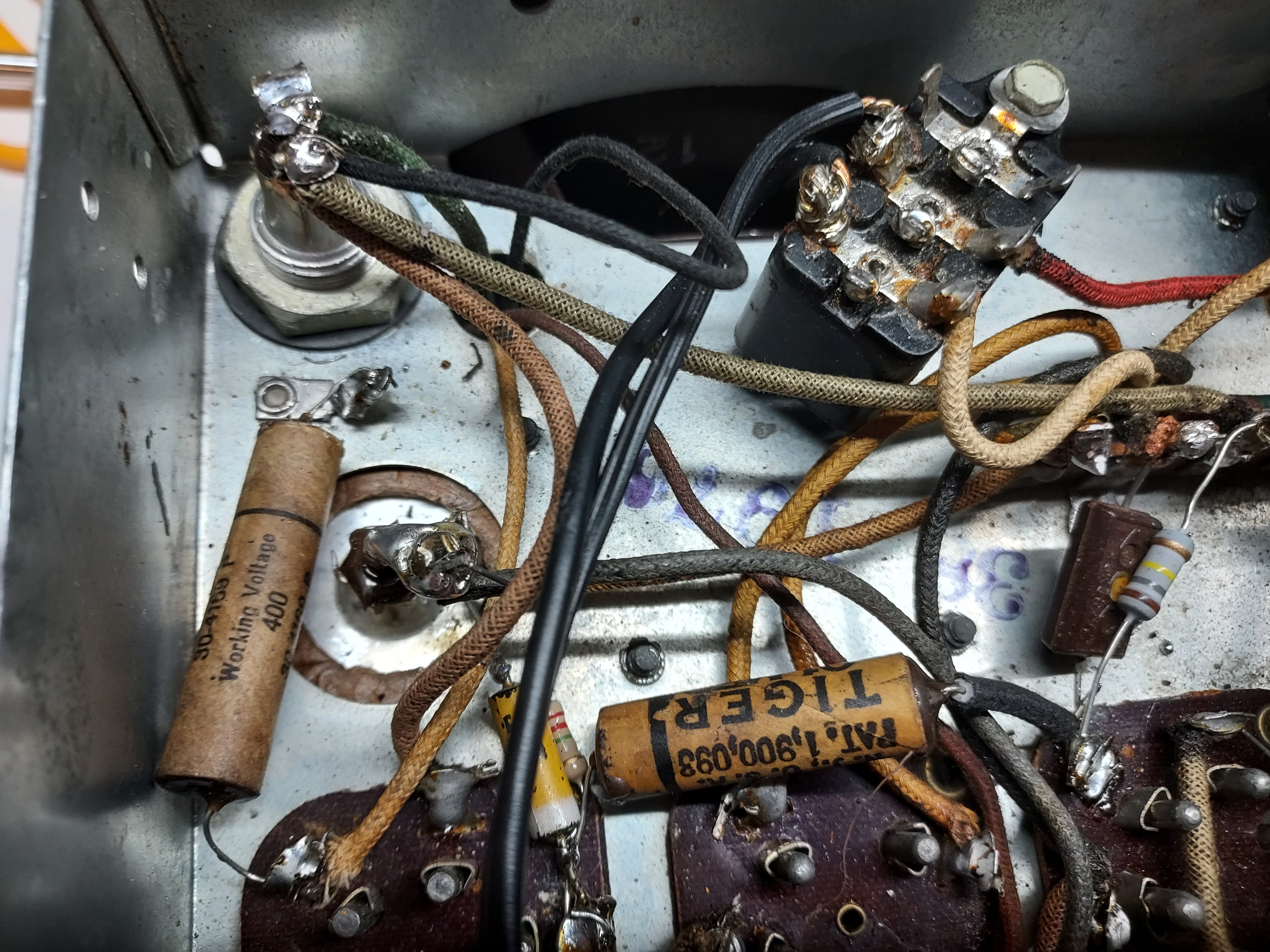
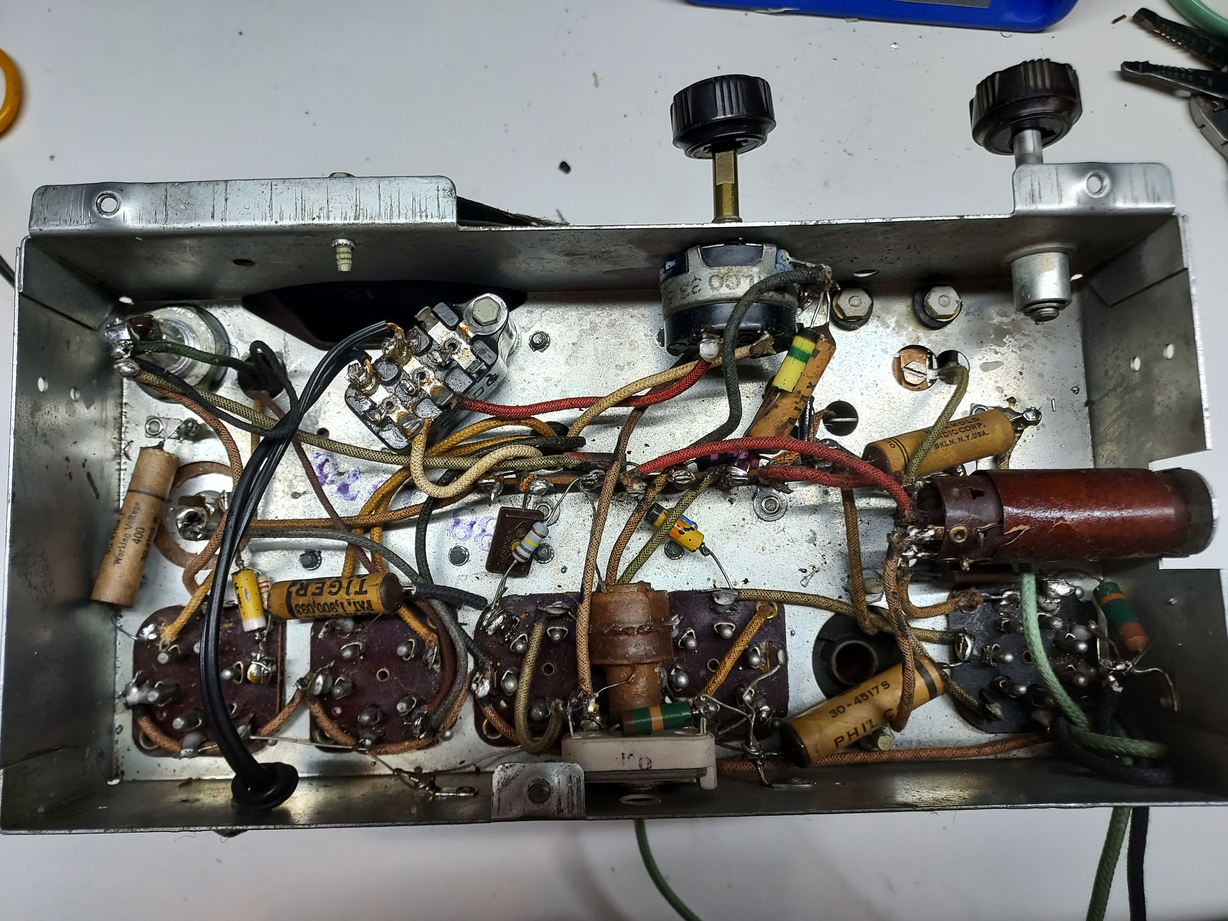
After this I pretty much just plugged it in 120V outlet and heard it receive. The voltages are very close to those shown at the chart, the rectified one is a bit higher (10V or so), because, well, it is today's Mains voltage, which is higher than 110V.
The alignment is pending.
The last two days' evenings I spent rebuilding the electrolytics.
First I had to drain them. I drilled two small holes diametrically across the bottom of both caps, one to drain the liquid and the other to let the air in.
After that I cut them open, gutted and soaked in white vinegar to get rid of some deposits and oxidation.
Then I rinsed and dried them, and after all this I started the "gefilte cap" dish.
First prep the 12uF cap: serialized two 22uF high-ripple Panasonic capacitors (22uF 450V, 560mA ripple at 120Hz).The resulting capacitance is 11uF, close enough.
Then wrap it in fish paper (to keep the cases from the shell), push into the shell, and insert two spacers to stabilize it inside the shell (also made from fish paper, a simple roll).
Then I put a copper rivet at the side of the shell, and soldered the negative lead to it.
This cap is now ready for epoxying the bottom back to it.
Now the 4uF cap. This is the second filter cap, and it could be larger than the original, so I use a high ripple 10uF 450V cap (170mA). This cap does not experience lots of ripple as it is preceded by the inductance (Field coil), so for all I care, it could be just a GP electrolytic.
Unlike the first cap, which is insulated from the chassis, this one uses the shell as the GND, and so the bottom of the shell could benefit from being solid, so the most natural place to cut is the cap's groove at the top.
Now I had to think of how to best connect the minus of the cap to the shell, so what I did was manufacturing a copper foil ring with a solder terminal, which would receive the inner cap's negative through a hole in the shell, while itself being between the shell's bottom and the chassis.
I soldered tug wires to the cap, to pull the leads through.
Then I trimmed and soldered the side lead.
Then I measured the capacitance.
This is how the caps look in citu, and the whole chassis after I also changed some broken antenna/GND wires.
After this I pretty much just plugged it in 120V outlet and heard it receive. The voltages are very close to those shown at the chart, the rectified one is a bit higher (10V or so), because, well, it is today's Mains voltage, which is higher than 110V.
The alignment is pending.
People who do not drink, do not smoke, do not eat red meat will one day feel really stupid lying there and dying from nothing.


![[-] [-]](https://philcoradio.com/phorum/images/bootbb/collapse.png)


